
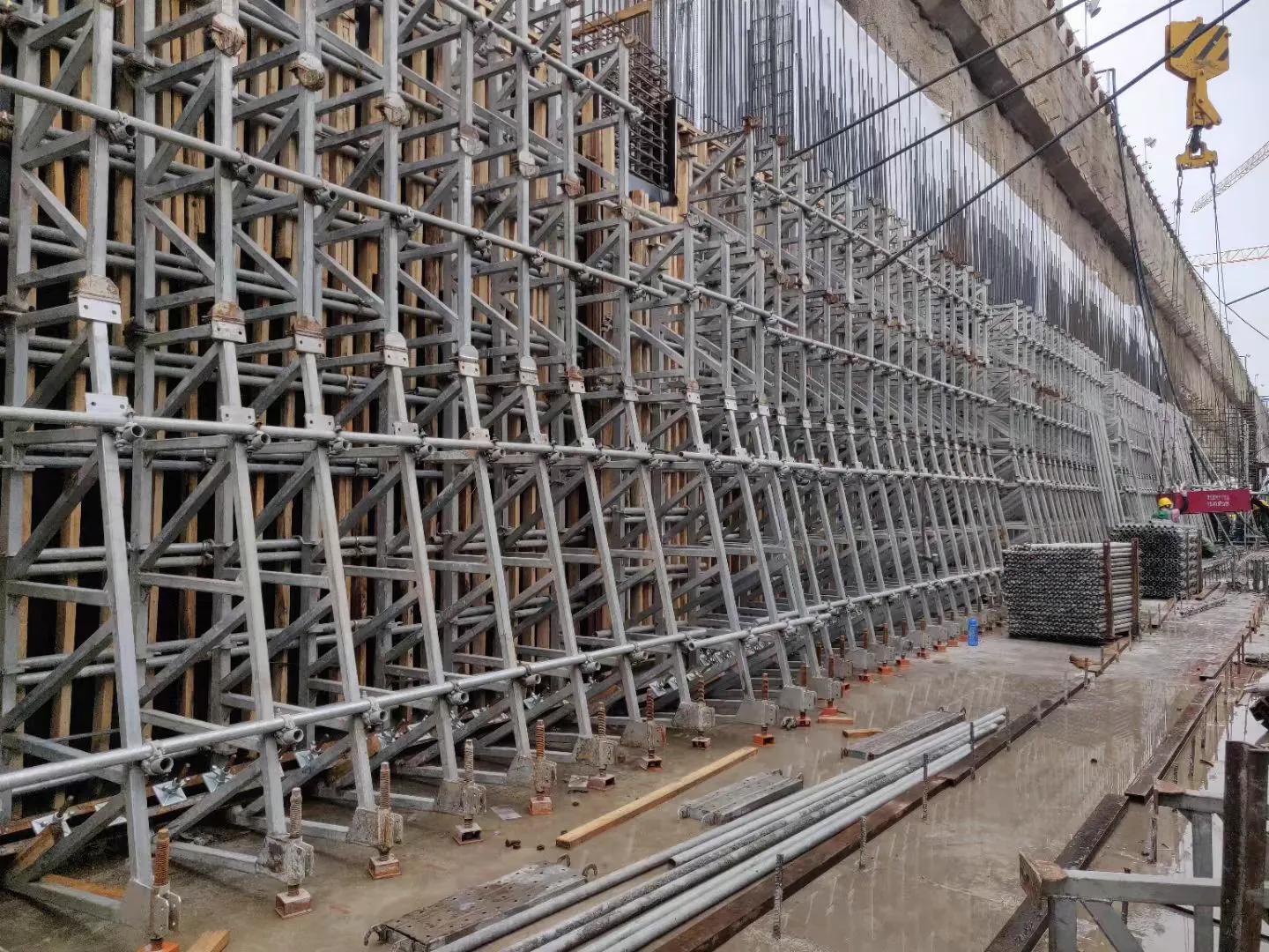
Formwork Panel Layout and BOM: Planning a Wall System from Dimensions to Procurement
> In brief > - Start with the concrete wall dimensions and pressure class, not the tie rod. > - Place formwork panels on a 600 mm or 300 mm modular grid to minimize joints. > - Derive the tie grid from the formwork panel lines, ensuring ties align with board intersections. > - Build the BOM by counting tie kits, walers, clamps, and consumables directly from the grid.
A wall is procured as a bill of materials long before any concrete is poured. The drawings demonstrate a rectangle of concrete, but the procurement configuration behind that rectangle is a long list of formwork panels, tie rods, nuts, cones, washers, walers, clamps, corner components and spacers, each sized from the same three wall dimensions. Most procurement problems on a formwork package do not start with a wrong price. They start with a formwork panel layout that was never actually drawn, so the tie pattern, the support count and the accessory list are each estimated separately and never reconciled.
This article treats panel layout as the control document: Panel layout is the arrangement of standard-sized formwork boards across a concrete wall surface on a fixed modular grid. Waler is the horizontal or vertical member that ties the tie rods together and spreads their load into the formwork panel surface. Bill of materials (BOM) is the consolidated quantity list that turns the layout into purchase lines. Get the layout right and the BOM writes itself; skip it and every trade on the project site quotes a different wall.
Panel layout is the arrangement of standard-sized formwork boards across a concrete wall surface on a fixed modular grid. Waler refers to the horizontal or vertical member that ties the tie rods together and spreads their load into the formwork panel surface. Bill of materials (BOM) means the consolidated quantity list that turns the layout into purchase lines. Tie rod is the component that connects the formwork panels through the concrete, securing them in place. Filler panel is the smaller formwork panel used to fill gaps at the ends of a wall, ensuring the modular grid remains intact.
1. Begin with the concrete wall dimensions, not the tie rod.
The only inputs required to initiate a layout are the concrete wall length, the concrete wall height and the concrete pressure class. Length and height establish the surface area and the standard board count. The pressure class, derived from the pour height and the mix, sets how far apart the ties may be spaced. The temptation is to start with the tie rod because that is the line item buyers recognise. The tie spacing, however, is a consequence of the formwork panel grid, and that grid is itself a consequence of the standard board dimension. Reverse that order and the ties land on lines that no standard panel reaches.
A standard plywood or steel-faced panel is manufactured on a module, most commonly 1.2 m by 2.4 m. Walls are therefore planned on a 600 mm or 300 mm sub-grid so that boards connect on a stud and a tie rod can sit at the meeting location. When a concrete wall length is not an exact multiple of the module, the short end is filled with a section panel rather than by shifting the entire grid. That shift breaks the tie alignment across every subsequent wall on the same project.
2. Place the formwork panels on the modular grid.
Lay the long dimension of the concrete wall along the 2.4 m board length first, because that minimises the number of horizontal joints and the number of walers required to bridge them. A 10 m wall takes four complete 2.4 m boards and one 0.4 m filler, all on one horizontal line. The vertical tie rows subsequently align at 2.4 m, 4.8 m and 7.2 m, with the filler edge closing the row. The height is constructed up in 2.4 m lifts until the top lift is shorter, which is normal and expected rather than a defect.
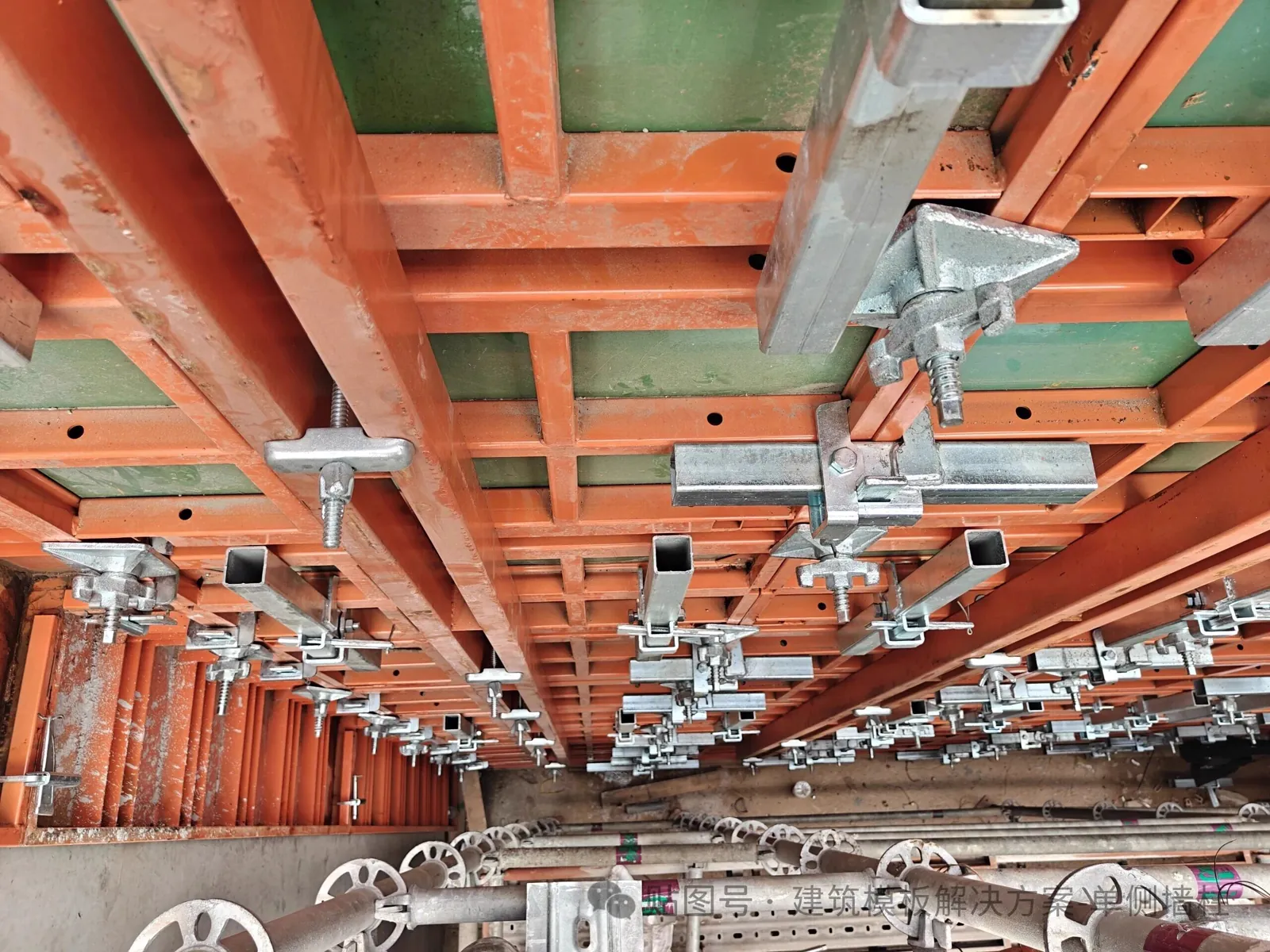
The filler panel at the end of a row is where most layout errors begin. A filler too minor to carry a tie rod becomes a dead panel that must still be procured and handled, while a mid-wall filler forces a tie row to jog. The discipline that avoids both is simple: maintain fillers at the concrete wall ends, maintain them at least one tie spacing wide, and treat the tie grid as fixed the moment the first board is placed.
Standard basis: ACI 347
3. Derive the tie grid from the formwork panel lines.
Once the formwork panels are placed, the tie rods land where the board lines intersect, because that intersection gives the strongest waler member connection and a flush cone seat. The maximum spacing between those crossings is determined by the concrete pressure, not by the standard board dimension, and that verification has to be made before the layout is accepted. Our article on concrete lateral pressure and tie spacing demonstrates how the concrete pressure class converts into a maximum grid, and the formwork panel layout has to accommodate it.
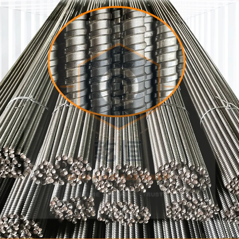
When the concrete pressure limit is tighter than the standard board module, the formwork panel grid stays on the module but an extra tie row is added inside a formwork panel utilising a Purpose-made insert, not by resizing the boards. When the concrete pressure limit is looser than the module, the ties are simply not placed at every crossing, which is the first location a BOM obtains more minor without the concrete wall obtaining weaker. The tie quantity takeoff method counts those placed ties directly from the modular grid rather than from a rule of thumb.
4. Build the tie-rod BOM from the modular grid.
Every tie crossing that carries a rod produces the same kit: a tie rod, two nuts, two washers, two cones or one cone and one plate, plus the water-stop parts below grade. The grid count is therefore the multiplier on the entire tie kit, and the accessory ratios fall straight out of it. A through-tie system returns almost everything, a lost-end tie returns nothing, and a five-section water-stop system returns roughly half, which is why the reusable share rather than the installed count drives the re-order trigger.
The nuts and washers deserve a dedicated line because they are consumed faster than the tie rods. A nut that is dropped, intersect-threaded or struck is discarded while its rod survives, so the wing and disc nut selection and the washer count should be ordered with a working margin even when the tie rod count is exact. The cast-iron water-stop nut and the standard disc nut are inventory items, and keeping them on the same order as the tie rods avoids a second shipment that costs more than the components.
Standard basis: EN 13670
5. Build the support BOM: walers, clamps and braces.
The tie grid additionally fixes the waler member layout, because a waler runs along each horizontal tie row and a clamp or tie plate locks the tie rod to it. The H20 timber beam load path explains how vertical beams carry the formwork panel to the waler member, and the waler member spacing is the same as the vertical tie spacing by construction. Double the tie rows and you double the walers; widen the tie spacing and you remove a waler line entirely, which is the second large lever on the BOM after the tie spacing itself.
For larger walls the steel waling system replaces timber and introduces section splices and connectors that are themselves line items. These are not optional trim; a steel waling run is a sequence of standard lengths, couplers and end anchors, each counted from the concrete wall length. The clamp that grips the tie rod to the wale is a minor component with a high loss rate, so like the nuts it is ordered with a margin and tracked through the inventory and recovery loop rather than forgotten.
6. Add the formwork panels, corners and consumables.
The panel line of the BOM is the standard board count from step 2, plus one filler allowance, plus corner and stop-end formwork panels for walls that turn or stop. Corners are the most commonly under-counted item because a drawing demonstrates a corner as a line, not as a special panel that has to be procured or fabricated. Every internal and external corner on the concrete wall is a formwork panel with its dedicated component number, and every opening larger than the tie spacing requires a box-out that consumes studs and braces.
Consumables close the material list: form-release agent by area, cone seals where water stop is required, and the plastic or steel cones that the tie passes through. None of these items is expensive alone, but each is a line that stops the pour if missing on the project site, so the BOM a procurement manager issues lists them with the tie rods rather than as an afterthought.
7. Worked example: a 10 m by 4 m by 0.30 m wall.
Consider a retaining wall 10 m long, 4 m high and 300 mm thick, poured in one lift after the concrete pressure verification. The surface is 40 m² and the panel count is nine complete 1.2 m by 2.4 m boards plus fillers. The 4 m height takes two 2.4 m lifts with a 0.8 m top filler, and the 10 m length takes four boards with a 0.4 m end filler. The tie grid is subsequently 8 columns by 3 rows, or 24 tie positions, which drives every fastener line below.
| BOM line | Basis | Quantity |
|---|---|---|
| Tie rods (D15) | 24 grid positions | 24 rods |
| Wing or disc nuts | 2 per rod | 48 nuts |
| Washers / plates | 2 per rod | 48 washers |
| Cones | 2 per rod | 48 cones |
| Vertical H20 beams | one per 0.6 m width | 17 beams |
| Horizontal walers | one per 1.2 m row | 4 walers |
| Rod-to-wale clamps | 1 per tie | 24 clamps |
| Panels (1.2 x 2.4 m) | surface coverage | 9 + fillers |
| Corner formwork panels | wall ends | 2 |
The table is the layout's core: every quantity tracks the same 1.2 m grid, so a 12 m wall takes the columns to 10, the rods to 30 and the walers to 5, with no new assumption. The complete procurement guide carries the same example into specification and supplier comparison.
8. What the layout means for the construction sequence.
A clean layout does more than dimension the purchase order; it sets the construct and the strip. Ties placed on a regular grid allow a work crew to operate a repeating configuration instead of a unique one at every location, and that configuration is faster to erect and strip, which is where the stripping man-hour estimate begins. Irregular grids force the crew to read each position, which slows both operations and raises the chance of a rod left in the concrete wall.
The reuse assumption belongs in the recovery programme, not in the first-wall BOM. A system detailed for ten turns still requires the complete first-wall quantity, but the cost structure only favours the reusable system once the recovery loop is actual, with bins, counts and a re-order trigger. The panel layout is what makes that loop possible, because every recovered component maps back to a position on the same grid.
9. Layout mistakes that inflate the BOM.
The first mistake is laying out the ties before the formwork panels, which produces spacing that no standard board reaches and forces custom formwork panels that cost more than the tie rods they carry. The second is placing fillers in the middle of a concrete wall, which jogs the tie row and adds a partial waler line that serves no structural purpose. The third is ignoring the concrete pressure verification until after the modular grid is drawn, which subsequently has to be redrawn with an extra tie row and a second waler, doubling the rework.
The fourth is counting only the tie rods. A procurement manager who issues a rod count and expects a concrete wall discovers that the walers, clamps, cones and corner formwork panels were never ordered, and the site procures them in a panic at a premium. The panel layout exists to prevent exactly this, because it is the one document where every line item answers to the same geometry. Treat it as the controlling document and the BOM, the purchase order and the recovery programme all stay consistent.
A short layout discipline keeps the purchase order from inflating:
- Set the formwork panel grid before any tie rod is selected.
- Hold fillers at the wall ends and keep them at least one tie spacing wide.
- Confirm the concrete pressure class before the tie grid is fixed, and carry panels, walers, clamps and cones on the same BOM line as the tie rods.
Site practice on formwork erection follows standards such as OSHA 29 CFR 1926.703 in the United States and EN 13670 for concrete execution in Europe, both assuming the support and tie system was laid out as one coherent configuration. The EU Construction Products Regulation and the underlying ASTM A615 reinforcing-steel references establish the material baseline that the BOM quantities are drawn against.
About us: Qianheng Formwork Fastener Factory manufactures D15 and D20 tie rods to Q235, Q345, 45# and QT450, and supplies the complete accessory set of wing nuts, disc nuts, washers, plates and cones that appears on the formwork panel-layout BOM. Inventory is approximately 300 t and inventory items ship within three days, so a layout change late in the programme can still be satisfied without a custom run. Our contact page carries the specification sheet and the current lead-time table, and the about page describes the factory and the quality system behind every line on the BOM, and this article was reviewed by the Qianheng Formwork Engineering team.