
Formwork Tie Quantity Takeoff: How Many Rods, Nuts and Cones a Wall Needs
At a glance: tie quantity takeoff converts wall area into an order quantity by dividing the area by the cell area of the tie grid, rounding upward, then applying accessory ratios, waste factors and recovery allowances for the poured system. Quantities get confirmed twice: arithmetically against the wall area, and structurally against the pressure the grid actually imposes. A grid that looks economical on paper can fail the lateral pressure check. Widening the cell multiplies the load per tie by the same factor, and can force a rod-diameter upgrade that costs more than the rods it saves. Quantities therefore get confirmed twice: once arithmetically against the wall area, and once structurally against the pressure the grid will actually impose. The hazard background of fluid concrete under pressure sits in OSHA's concrete construction eTool, and the conformity context for the specification sits within the EU construction-products framework.
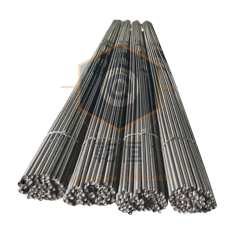
Ordering tie hardware is one of the few procurement decisions where a two-minute arithmetic error becomes a site stoppage. Under-order and the pour waits, while over-order leaves the surplus sitting in a container for the next project, which for an export programme means freight and duty paid twice. This guidance sets out the takeoff arithmetic from wall area to tie count, the accessory ratios that ride along with each tie, and the waste and recovery factors that convert a theoretical count into a defensible order quantity. It also covers the pressure check that constrains how wide the grid may be opened.
Takeoff is the process of converting a measured wall area into a complete bill of quantities for every item that the tie system consumes, not only the rod. Cell area refers to the area served by each tie, calculated as the product of the horizontal and vertical spacing between adjacent ties. Allowable working load is the rated yield of the tie rod divided by the project safety factor, used to ensure the grid can withstand the load per tie. Accessory ratio means the number of nuts, washers, plates, and cones required per tie, which varies by system and must be included in the order. Waste factor is the percentage of additional ties and accessories ordered to account for cutting, thread damage, and other losses during construction.
1. Why takeoff errors cost more than the steel.
A tie rod constitutes a low-value item carrying a schedule-critical function, and the rod itself is rarely the expensive part of the delay. The crane, the crew and the pump are all standing while a shortfall is resolved, and on a remote site the replacement freight can exceed the value of the original shipment.
The second error is quieter and considerably more common: procurement calculates the tie count correctly, then orders the rods alone. The nuts, washers, plates and cones arrive later or not at all, and the wall cannot be tied even though the primary item is on site. This happens because each tie system carries its own accessory ratio, and the ratio is rarely printed on the rod datasheet.
Takeoff is the process of converting a measured wall area into a complete bill of quantities for every item that the tie system consumes, not only the rod. The bill is what gets priced, ordered and reconciled on delivery, so it has to include everything the pour will consume.
2. From wall area to tie count: the arithmetic.
The tie count follows from the grid the designer specifies. A grid is described by the horizontal and vertical spacing between adjacent ties, and each tie serves the cell area that surrounds it. The count therefore constitutes the wall area divided by the cell area, rounded upward, because a partial cell still requires a tie.
For a wall of one hundred square metres, the count changes substantially with the grid:
| Grid (H x V) | Cell area | Ties per 100 m2 | Round up |
|---|---|---|---|
| 0.6 x 0.6 m | 0.36 m2 | 277.8 | 278 |
| 0.6 x 0.9 m | 0.54 m2 | 185.2 | 186 |
| 0.75 x 0.75 m | 0.5625 m2 | 177.8 | 178 |
| 1.0 x 1.0 m | 1.00 m2 | 100.0 | 100 |
| 1.2 x 1.2 m | 1.44 m2 | 69.4 | 70 |
Two refinements matter on a real wall. First, edges and corners resist a different pressure pattern from the field of the wall, so most specifications tighten the grid within roughly one tie spacing of a free edge or a corner. The takeoff should carry a separate line for those denser zones rather than averaging them into the field count. Second, openings such as windows and penetrations remove area from the denominator but leave the perimeter ties in place, so the saving is smaller than the opening area suggests.
The ACI 347 formwork practice adopts the hydrostatic starting point before applying temperature and pour-rate reductions, so the grid derived from the tables below is the conservative ceiling from which to detail. The spacing arithmetic behind the grid selection is developed further in concrete lateral pressure and tie spacing, and the rod diameter that pairs with each grid is covered in sizing D15 and D20 tie rods.
Standard basis: ACI 347 formwork practice
3. The pressure check that constrains the grid.
A wide grid reduces the rod count, and that constitutes the entire temptation. The counterweight is that the load per tie scales with the identical cell area, because doubling the cell doubles the force each rod must resist. The grid is therefore only valid while the load per tie stays below the allowable working load of the selected rod.
Normal reinforced concrete weighs approximately 24 kN/m3 (see Engineering Toolbox concrete properties), so a four metre lift imposes roughly ninety-six kilopascals at the base before any temperature or pour-rate reduction. Multiplying that pressure by the cell area gives the load per tie, which is then compared with the working load, meaning the rated yield divided by the project safety factor of two to three.
| Cell area | Load per tie at 96 kPa | D15 working (SF 2) | D20 working (SF 2) | Verdict |
|---|---|---|---|---|
| 0.36 m2 (0.6 grid) | 34.6 kN | 75 kN | 115 kN | D15 sufficient |
| 0.54 m2 (0.6 x 0.9) | 51.8 kN | 75 kN | 115 kN | D15 sufficient |
| 1.00 m2 (1.0 grid) | 96.0 kN | 75 kN | 115 kN | D15 short, D20 required |
| 1.44 m2 (1.2 grid) | 138.2 kN | 75 kN | 115 kN | D20 marginal |
Allowable working load is the rated yield divided by the safety factor, and it is the only figure a grid may be checked against. Our datasheets indicate a D15 system near one hundred fifty kilonewtons yield and a D20 near two hundred thirty kilonewtons. The verification methodology applies batch tensile testing to every finished part, with the calibration basis documented against NIST's material measurement discipline.
The break-even is visible in the table. Moving from a seven hundred fifty millimetre grid to a one metre grid saves seventy-eight rods per one hundred square metres. It also pushes the load per tie above the D15 working load and forces a D20 upgrade across the whole wall. Whether that trade wins depends on the price gap between D15 and D20 against the value of 78 rods, and on an export job it usually loses. The practical rule is to price the grid, not the rod: ask the supplier for both options at the same wall before committing.
4. What arrives with each tie: the accessory ratios.
Each tie system consumes a different set of components at every point, and the ratio is what turns a tie count into a complete order. The ratios below reflect the component sets our own systems are supplied in, and they should be confirmed against the supplier's packing list before the order is released.
| Component | Reusable through-tie | Single-sided (climbing cone) | Five-section water-stop |
|---|---|---|---|
| Tie rod | 1 | 1 | 1 core + 2 end sections |
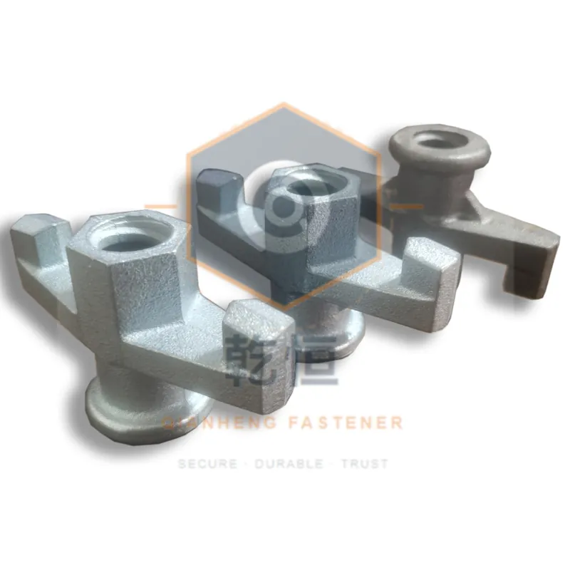
| Wing / combination nut | 2 | 2 | 2 |
| Washer / plate | 2 washers | 1 plate + 1 cone assembly | 1 stop element on core |
| Recovered after pour | Rod + nuts | Rod + cone + plate | 2 threaded end sections |
| Typical waste factor | 3 to 5 percent | 5 to 8 percent (cones lost) | 3 to 5 percent |
The butterfly nut and combination nut pages show the thread forms that pair with each rod diameter, and the climbing cone assembly page details the lost-end recess the single-sided system requires at every stage.
The single-sided system deserves particular attention in the takeoff, because the cone and the plate are consumed on a different basis from the rod. The rod and the nuts return to the next wall; the cone assembly is removed and cleaned but is routinely dropped, buried or written off, which is why its waste factor runs higher than the rod line. The cost-per-use arithmetic for those consumable-adjacent items is worked through in plastic or steel cones.
5. Waste, loss and recovery factors.
The theoretical count is never the final order quantity, and three adjustments sit between them, each of which is measurable rather than guessed once a programme is running.
First, cutting and thread damage: rods are cut to length on site, threads get bruised during handling, and a bent rod is scrapped rather than straightened into a structural position. On a well-run site this runs at three to five percent of the rod count.
Second, genuine loss: nuts and washers walk off site, cones get cast into the wrong lift, and small items disappear into the rubble. This is the reason the accessory quantities are rounded up more generously than the rod count.
Third, recovery: a reusable through-tie returns the rod and the nuts to the next pour, so the purchase covers the first wall and the logistics cover the remainder of the programme. The five-section water-stop configuration returns the two threaded end sections while the central core stays in the wall. The core quantity is therefore ordered per wall, but the end sections are ordered as a one-off pool sized to the programme. The inventory and recovery arithmetic that governs that pool is set out in formwork hardware inventory and recovery.
A worked recovery example makes the pool sizing concrete: A programme of twenty walls of one hundred square metres each on a six hundred by nine hundred millimetre grid requires three thousand seven hundred twenty tie points. The water-stop cores are ordered once at that full quantity, because every point retains its core. The threaded end sections are ordered as a pool with a recovery allowance, since each section cycles back within the pour sequence. That pool is sized to the peak concurrent demand plus the damage and loss factor, not to the total point count.
Standard basis: EN 13670
6. Building the RFQ quantity table.
The deliverable of a takeoff constitutes a table rather than a single number. A table lets the supplier price the complete system, flag substitutions, and confirm the accessory ratios against their own packing standard, which is where most quantity disputes actually surface.
| Line | Item | Basis | Quantity |
|---|---|---|---|
| 1 | Tie rod, D20, per length schedule | 178 points at 0.75 grid | 178 + 5 percent |
| 2 | Wing nut, matching thread | 2 per point | 374 |
| 3 | Washer | 2 per point | 374 |
| 4 | Plate / cone assembly | Per system ratio | Per wall count |
| 5 | Edge-zone ties, tightened grid | Separate denser zones | Per drawing |
| 6 | Spare set, damage and loss | 3 to 5 percent | Per programme |
When the table goes into the RFQ, four inputs make it quotable without a second round of questions. Those inputs are the wall area and the grid, the lift height and pour rate, the system type with its accessory ratio, and the programme length that decides whether recovery is priced. Writing those four into the enquiry is the difference between one accurate quotation and three vague ones, and the structure for doing so is set out in how to write a fastener RFQ.
We hold approximately 300 t of fasteners in stock and dispatch stock items within 3 days; custom diameters, lengths and coatings run 7 to 15 days. Every finished part is tensile-tested against its specification and the result travels with the batch. Trade terms are EXW, FOB, CIF or DDP depending on who controls the freight, and export packing utilises VCI paper and strapped crates so the accessory counts arrive as packed rather than as a sorted pile.
For a programme takeoff, sending the wall schedule and the grid to our engineering team before the order is placed produces a checked quantity table. A second set of numbers to compare against your own is cheaper than either a site stoppage or a container of surplus.
FAQ.
How many tie rods does 100 m2 of wall need?
It depends on the grid. At a six hundred by six hundred millimetre grid the answer is two hundred seventy-eight ties; at seven hundred fifty by seven hundred fifty it is one hundred seventy-eight; at one metre it is one hundred. Divide the wall area by the cell area and round up, then add three to five percent for cutting damage, thread bruising and site loss, and confirm the widest cells against lateral pressure before ordering.
What accessories come with each tie rod?
For a reusable through-tie the ratio is one rod to two wing nuts and two washers. A single-sided climbing-cone point needs the rod, a cone assembly, a plate and two nuts. A five-section water-stop point is one central core plus two threaded end sections, and the two ends come back after the pour for reuse on the next wall.
Can I widen the tie grid to reduce the number of rods?
Only within the pressure limit, because widening the cell multiplies the load per tie by the same factor. A one-point-two metre grid on a four metre lift puts roughly one hundred thirty-eight kilonewtons on each tie, which is above the D15 working load and close to the D20 limit. Widening beyond that point forces a rod upgrade that usually costs more than the rods it saves.
---
About the author — Qianheng's formwork engineering team designs and tensile-tests tie-rod systems for contractors across the EAEU, the Middle East and Southeast Asia. *Reviewed by our quality engineer before release.*
About us: This article covers formwork tie quantity takeoff, including calculations and pressure checks. Our engineering team ensures the accuracy and practicality of the content. Our contact page provides a direct line to our technical support, and the about page documents our company's history and capabilities. This article was reviewed by the Qianheng Formwork Engineering team.