
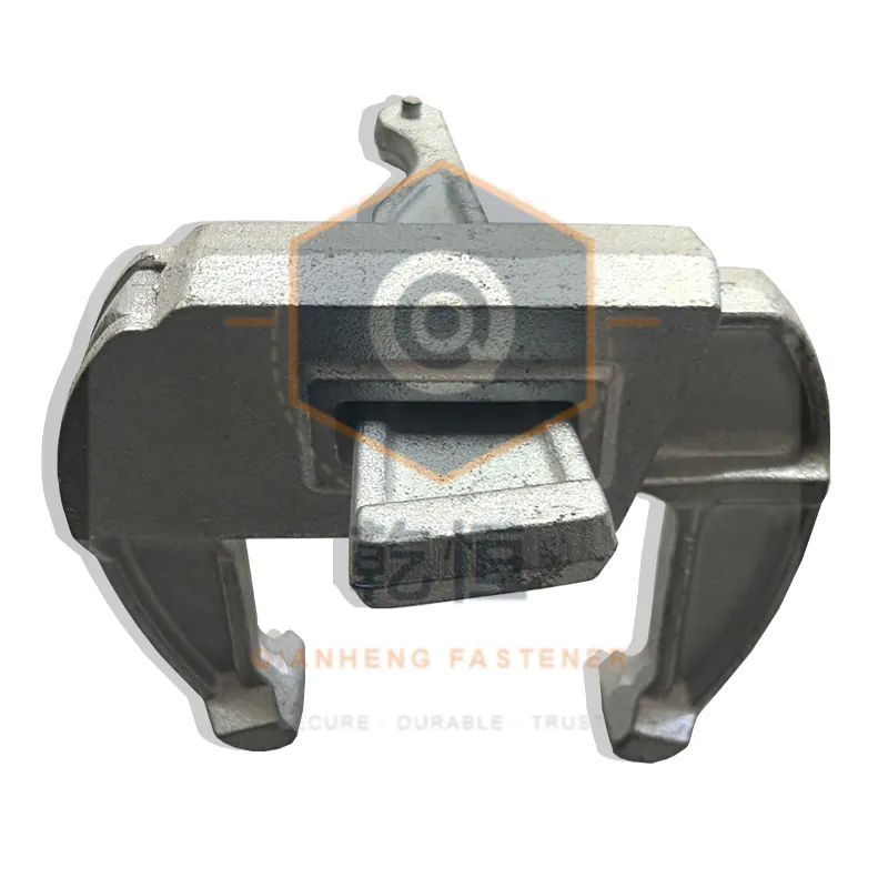
Timber beam systems are assembled from many small parts, and the capacity of the assembly is set by the weakest connection — not by the beam. Knowing the load path tells you where to look.
The path
Fresh concrete pressure acts on the panel skin, which spans to the H20 beams. Beams span to walers, walers span to tie rods through the panels. Vertical loads from slabs travel through beams to props or the supporting structure. Clamps connect beams to walers or to other beams; they transfer shear, and they are often loaded in a direction the assembler did not assume.
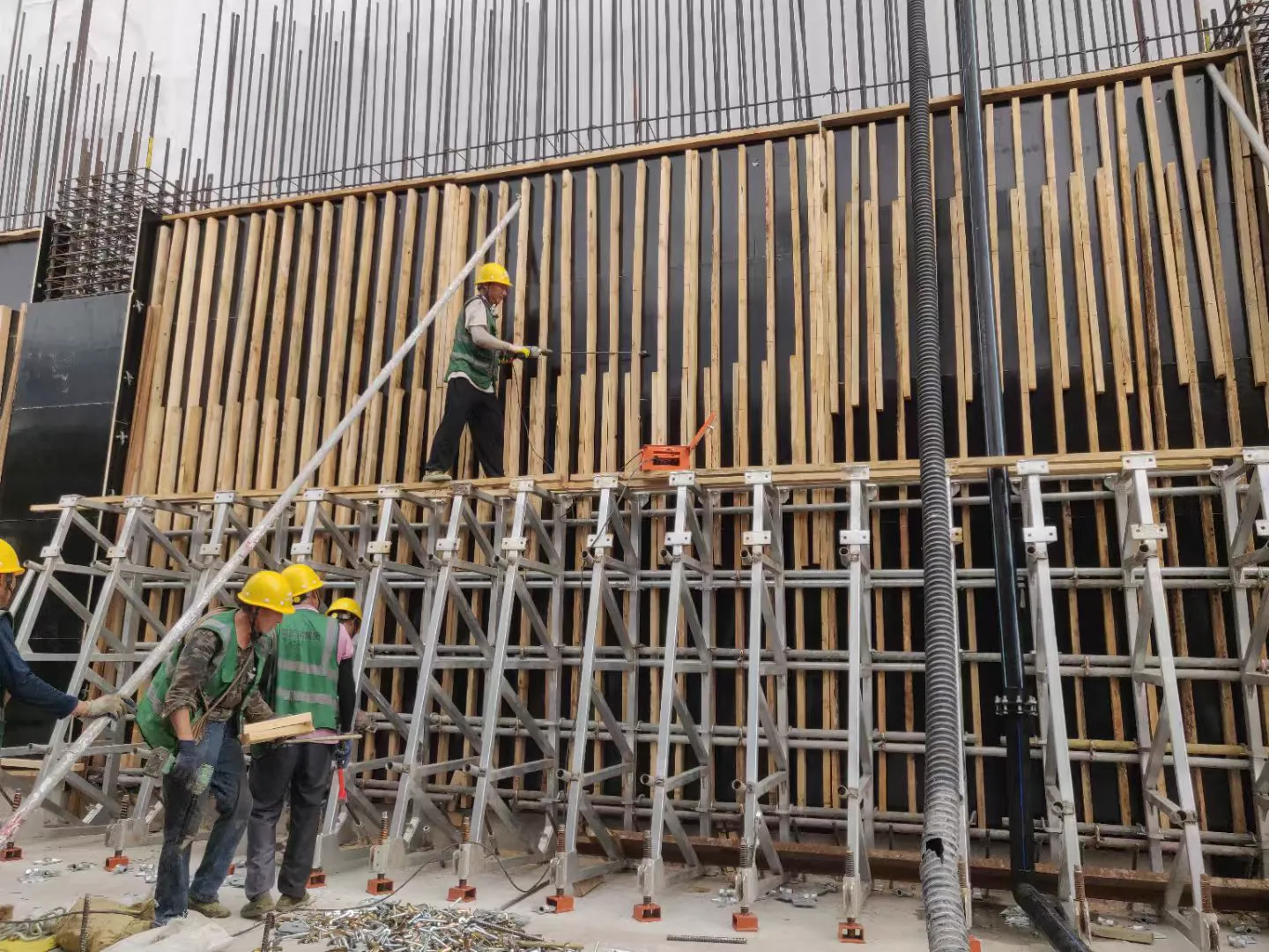
The usual weak links
CLAMP SLIP is the most common. A clamp rated for a holding force achieves it only at the specified tightening torque, with clean and dry bearing surfaces. Overtightening crushes timber and reduces bearing area; undertightening lets the beam move under the pour and the panel deflects.
BEARING CRUSHING at the beam-to-waler contact. Timber has limited bearing strength perpendicular to grain; a small contact washer concentrates load and dents the beam. Repeated reuse turns a dent into a split.
BEAM SPLICE LOCATIONS. A beam spliced over a waler has its maximum curvature at the splice. Splices belong where moment is low — in practice near a support.
WALER JOINTS. A waler spliced between ties behaves as two cantilevers, quite unlike a continuous beam. Joints must be designed, not improvised.
Assembly rules that hold up
Tighten clamps to specified torque with a torque wrench on a sample, then train by feel against that sample. "As tight as possible" fails in both directions.
Keep bearing surfaces clean. Concrete dust and hardened release agent increase slip at a given torque.
Do not let a waler bridge a gap to a beam without a bearing plate; point loading at an edge is how beams split.
Check tie positions against the waler splice plan, not only against the panel grid.
Reuse inspection
BEAMS: split ends, crushed bearing zones, longitudinal cracks near ends, moisture damage. A beam with a split within one depth of the end should be cut back and re-capped or retired.
CLAMPS: thread condition, deformation at the jaws, and wear that changes clamping geometry. Measure jaw opening on a sample against the original dimension.
WALERS: dents at tie holes, elongation of holes, bends. An elongated tie hole reduces bearing and lets the tie move under load.
PROPS: thread condition, base plate deformation, pin wear. Prop capacity is usually quoted for a specific extension range; extend beyond it and capacity falls non-linearly.
Procurement notes
Ask for the rated capacity of each component and the conditions under which it applies — torque, bearing surface, extension range. A system capacity quoted without conditions cannot be used in a calculation.