
A steel waler — also called a waling, soldier or soldier beam — is the horizontal member that turns a formwork panel into something that can resist concrete pressure. Panels are thin by design and cannot span between tie rods on their own. The waler picks up the pressure line, distributes it along its length, and delivers it into the tie rods at regular intervals. Get the waler wrong and the failure does not announce itself: the panel bows, the tie rods pull out of the concrete cone, and the wall you get is not the wall you drew.
This article works through how to specify a waler system properly: section selection, the load path, splice and bracket details, deflection limits, coating, and the clauses worth putting on the purchase order. It is written for the procurement manager or site engineer who has to sign for the steel and then live with it.
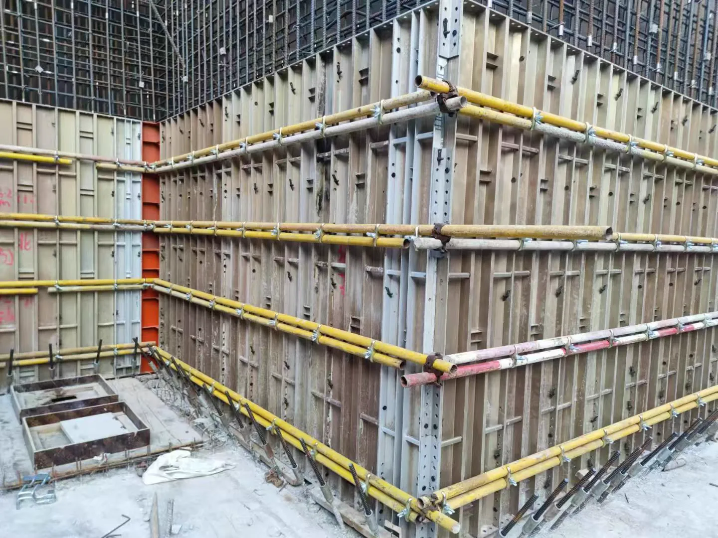
The load path, stated plainly
Concrete pressure on a vertical panel is a triangular distribution: nothing at the top where the concrete has not yet arrived, maximum at the base where the full height of concrete is pushing horizontally. The panel takes that pressure and hands it to the walers, which are vertical members spaced across the form face. Each waler spans horizontally between tie rods, picking up panel pressure along its length and passing it into the tie rods as concentrated reactions.
Three things follow from that geometry, and they drive every specification decision that follows:
- The waling spans between tie rods. Its bending demand is set by the tie rod spacing and the panel pressure it collects. Doubling the tie rod spacing more than halves the waling's effective span and roughly doubles its bending moment.
- Tie spacing is a waling decision as much as a panel decision. The panel must be strong enough to span between walers, and the waling must be strong enough to span between ties. Whichever member fails first defines the whole system's capacity.
- Deflection, not strength, is often the limit. Concrete that leaks through a bowed panel, or a finished surface with visible ripple, is a rejected pour even when nothing actually broke.
Why double-channel sections dominate
Walers are almost always built from two channel sections back to back. That is not fashion; the pair solves a specific problem that a single channel does not.
A single channel loaded eccentrically — which is what happens when a tie rod pulls at one flange and the panel pushes between ties — has very little torsional stiffness. It twists, the panel loses its edge support, and the effective bending strength drops well below the catalogue value. Two channels separated by a fixed distance and tied together by brackets or a spacing rail resist that twisting: the two channels behave as a couple, and the section modulus is close to that of a solid section of the same overall depth.
The specification mistake is comparing channel count instead of section properties. Ask for the section modulus (W, in cm3 or mm3) at the section being quoted, the overall depth, and the twist behaviour of the assembly. Two channels of 100×50×4 mm give a very different result depending on whether they are bolted at 300 mm or600 mm centres and whether a continuous spacer is welded between them.
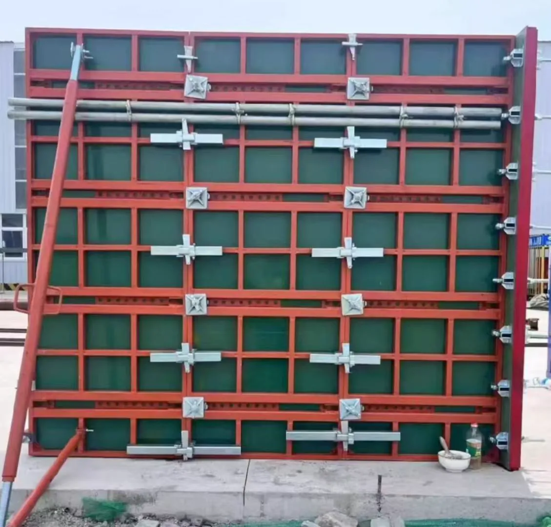
Section selection by load and span
Once the tie rod spacing is fixed, section selection becomes a straightforward check with two outputs: bending capacity and deflection. Deflection is what limits most walls.
For a simply supported beam under a uniformly distributed load:
- Bending moment, M = wL2/8
- Maximum deflection, δ = 5wL4 / (384EI)
where w is the load per unit length collected by the waler, L is the span between ties, I is the second moment of area of the assembled section, and E is 235000 N/mm2 for steel.
Two practical rules follow. First, deflection scales with the fourth power of the span, which is why halving tie spacing is so much more effective than adding steel. Second, stiffness (EI), not strength, is what governs most wall walers — a heavier section that is still too deep-span will deflect past the limit before it reaches its bending capacity.
Typical practice on commercial building work keeps deflection in the low single-digit millimetres at the maximum panel span, with the exact limit usually set by the finish specification: a fair-faced architectural surface has a tighter tolerance than a concealed wall. Check what your own specification calls for before selecting the section, because this number decides the whole answer.
Splice detail
A long wall run cannot be made from one length of waler. The splice is where the bending capacity either continues or stops.
The design question is whether the splice preserves the section's bending capacity. Two approaches work:
- Butt weld with a bolted cover or a welded stiffener. The plates transfer load by direct bearing and the weld transfers shear. This gives reliable bending continuity if the plates are sized for the full moment.
- Bolted splice plates. Acceptable where access for welding is poor, but the bolt group must be checked for the shear implied by the load transfer, and the plate must not reduce the effective section modulus.
The placement matters more than most buyers expect. Locate the splice roughly one bay in from the panel end, away from the dense tie rod group, so the splice sits in a region of lower bending moment. A splice at the panel centre, right where tie rod spacing is tightest, puts the connection at the highest moment in the run.
Brackets and connections
The bracket that ties panel to waler carries a vertical shear at that joint. It does not carry the full lateral concrete pressure — the waler does that, spanning between ties. Buyers frequently specify brackets for the full pressure, which over-specifies the connection, adds cost, and adds no capacity, because the waler would have failed before the bracket did.
Three bracket details that cause real problems:
- A bracket that only grips the flange edge. Under inward pressure the panel tends to rotate, and a single-edge grip lets it rock. A two-point bearing or a wedge that locks the panel to the waler is worth the small extra cost.
- Weld-on brackets with no gusset. The weld toe is the fatigue crack starter; every site weld-around is a potential defect.
- Bracket holes that force site drilling into the waler. Drilling into a load-bearing member on site introduces stress concentration and coating damage. Specify holes in the drawing.
Coating and the rental cycle
For a rental fleet, hot-dip galvanizing to a defined coating mass is the working default. It survives repeated wet-dry cycling and handling abrasion better than paint, and unlike zinc flake it is not destroyed by a single scrape. Zinc flake (Dacromet-type) systems give better corrosion resistance but are damaged by site abrasion and repeated handling, which makes them a poor match for rental stock that will be struck and re-deployed many times.
Two clauses worth having on the purchase order:
- Specify coating mass in g/m2, not "galvanized". A minimum of roughly 70 g/m2 is a common floor for non-immersed structural steel; higher duty asks for more.
- State whether cut edges, holes and weld seams are coated. Hot-dip galvanizing cannot reach inside a reamed bolt hole, and the exposed edge is exactly where a waling fails first.
What to put on the purchase order
The clauses that reliably prevent disputes on waling supply:
- Section properties, not just a section name. Ask for the section modulus W, the overall depth, and the assembly detail (channel spacing and bracket or spacer centres). "100×50×4 double channel" alone is not a specification.
- Coating mass in g/m2, plus whether edges, holes and welds are covered.
- Material grade stated against the standard you intend to certify against.
- Hole positions and diameters on the drawing, with a tolerance. Site drilling into a waling is not acceptable.
- Weld procedure and acceptance class for anything that is welded at the factory, including whether it is by a coded welder.
- Flatness and straightness tolerance over the supplied length. A waling with 3 mm of sweep over 6 m will not sit flat against a panel, and the gap is where the grout leak starts.
- Match with the tie system. If the waler carries the tie rods, state the tie rod grade and spacing in the same document so nobody has to infer the other half of the calculation.
Where the detail decides the job
On a single-sided wall, where the formwork face has no concrete behind it to react the pressure, the waler and the bracing take the full lateral load as a spanning system. That arrangement puts the waler at its worst case and is where section selection earns its keep. Photos of that arrangement — single-sided bracing grids and wall bracing — are worth reviewing against the drawing before ordering, because the waler here is a structural member and not a secondary framing piece.
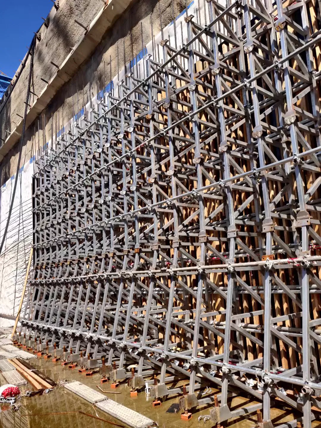
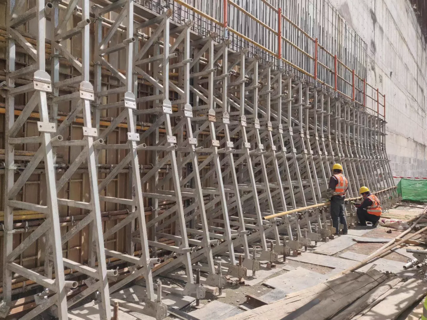
On ordinary double-sided wall formwork the waler is less critical, and the tie rod usually governs. That is the point at which the five-section water stop tie rod becomes the more expensive decision, because it is specified for the water-exclusion requirement rather than for strength.
What to check before ordering
- Does the quoted section modulus match the calculated bending demand at your actual tie spacing?
- Does the deflection at that span meet your finish tolerance, not just the strength limit?
- Is the assembly detail (channel spacing, bracket centres) stated, or is the supplier free to choose?
- Are coating mass, edge coverage and hole protection specified numerically?
- Are the holes drawn, with a tolerance, so nobody drills on site?
If any of those five answers is "not stated in the quotation", the cheapest place to fix it is the purchase order, not the site.