
Adjustable Steel Prop Legs: How Extension, Overlap and Base Plates Decide Whether a Slab Stands Up
> In brief > - The adjustable leg is a load path, not a length. > - Working capacity depends on the extension and the base plate. > - The specification has to say which configuration the rating applies to.
A slab falsework is procured as a number of props, and that quantity comes from a simple division: soffit area divided by the bearing area of a single prop leg. That division is where most shoring packages go wrong, because it treats every prop leg as identical when one is in fact three separate components carrying three quite different demands. An adjustable steel prop leg is an outer tube, an inner tube that slides inside it, and a locking device that holds the overlap between them. The outer tube takes compression and buckling, while the inner tube takes compression and the bending that arrives from a slab edge pushing outward. The locking device carries whatever the inner tube tries to slide out with. Buy on the outer tube alone and you have purchased nothing more than a length of pipe.
This article therefore treats the prop leg as a fully specified structural component rather than as a counted accessory. Extension range is the span the prop covers between its shortest and longest setting, and the permitted capacity at the long end is invariably the worst. Minimum overlap is the length of engagement remaining between the two tubes with the pin inserted, and this is the figure the manufacturer actually certifies. Base plate is the component that arrests the whole assembly sliding or punching through at its base. Get these three right and the prop is a known quantity in the falsework design; get them wrong and the soffit height you set on day one is not the soffit height you pour.
In brief: a prop leg is specified by three numbers that must travel together, namely the extension range, the minimum overlap and the base plate construction. The load class matters considerably more than the price per prop, because a cheap prop at full extension is simultaneously the cheapest and the most dangerous object on the site. A shoring lot is inspected on defect rate at the point of delivery, because a large lot of single-value items either mostly works or mostly does not.
The three components behave quite differently under load, and the split between them explains most of what subsequently goes wrong in service:
| Component | Load it carries | How it fails | What a buyer must state |
|---|---|---|---|
| Outer tube | Compression | Buckles when effective length exceeds the section | Section size and pinned length |
| Inner tube | Compression and bending from lateral load | Bends at the exposed length above the outer tube | Exposed length at working extension |
| Lock device | The slide-out force of the inner tube | Walks or releases under lateral movement | Lock type and pin hole pitch |
| Base plate | Vertical bearing and horizontal shear | Slides on soft ground or punches in | Diameter, thickness, shear geometry |
Extension range is the span the prop covers between its shortest and longest setting. Minimum overlap refers to the length of engagement remaining between the two tubes with the pin inserted. Base plate means the component that arrests the whole assembly from sliding or punching through at its base.
1. Why a prop is three components and not one length.
The single most common specification error is treating a prop leg as a single telescopic length, and why that matters is that the three components fail in three quite different ways. It is not a single length at all: it is an outer tube of one diameter, an inner tube of a smaller diameter that slides inside it, and a lock that fixes the position of the inner tube within the outer one. Each of those three components has its own failure mode, and they do not fail at the same moment.
The outer tube fails by elastic buckling, and it buckles once the effective length exceeds the section's permissible value. This is why prop outer tubes have a noticeably heavier wall than the inner ones, even though the inner tube carries the higher compressive stress. The inner tube is the component that actually fails in bending. It carries the exposed length between the bottom of the outer tube and the head plate, and that is where a lateral load from a slab edge or a pump hose gets introduced. A prop that is extended to its maximum is simultaneously at its worst buckling length and its worst bending length, which is the reason the capacity of any prop falls as it is extended.
The locking device is the third of those components, and it is also the one that generates all the paperwork. A prop extended to its maximum that then loses its pin is not a prop at reduced capacity but a sudden and complete capacity loss while the slab bears on it, so the locking geometry determines whether a prop leg suits a vibrating pour or is restricted to a static soffit.
2. The load class is the specification, and the price per prop is not.
A prop leg arrives with a capacity marking, and the marking is frequently the least trustworthy part of the delivery. What a buyer needs is a capacity at the extension the job actually uses, tested as a system, not a maximum number quoted for a particular arrangement.
European practice addresses this through EN 13163, which tests adjustable steel props for constructional temporary works and grades them into classes. Outside Europe, the reference point for temporary works loading is the OSHA scaffolding standard 1926.451. Its appendix A sets out the load classes a competent person applies when erecting a temporary support structure. The grading runs from the lightest duty to the heaviest, and each class ties a permitted working load to a stated extension range. This matters commercially because it makes the capacity a property of the certified product rather than a marketing claim about a component. In the United States the equivalent discipline comes from the temporary works provisions in OSHA 29 CFR 1926.703, which treat formwork and its supports as a load-supporting structure that must be capable of carrying the loads without unacceptable deformation.
For a procurement engineer the practical translation of all of this is straightforward enough. Name the class in the purchase order, name the test standard, and then read the capacity figure at the extension that the soffit height actually requires. A prop leg specified as class X but priced as if every class were equal will arrive as the lighter duty article, and a lighter duty article carrying a class marking is still simply a lighter duty article. This is one of the situations where the fastener procurement specification principle applies completely unchanged to a shoring component: the specification has to name the value, and the value has to remain independently checkable on delivery.
3. Minimum overlap is the number that actually governs.
Which of the three numbers actually governs the capacity? It is the minimum overlap, and it is also the one most often left out of a purchase order altogether. The minimum overlap is simply how much of the inner tube remains inside the outer tube with the lock engaged. At that setting, the two tubes behave as a single structural member and the assembly can carry its rated load. Below that setting, the assembly behaves as two tubes held by a pin, and the capacity depends on bending of the inner tube and on bearing at the pin hole.
This produces a practical rule that surprises buyers who have been counting props by area. The number of props required is set by the bearing area at the working extension, not by the nominal bearing area of the prop. A prop that must extend to 3.4 m on a 3.5 m soffit may only have 2.6 m of working range once the minimum overlap is respected. It is specifically at 2.6 m that the prop must be counted. If the soffit height exceeds the working range entirely, the answer is not a longer prop leg. The answer is a post-shore or an entirely different falsework system, and the slab formwork props and beams layout approach is where that decision belongs.
The gap between nominal reach and usable working range is worth writing down explicitly, because it is precisely the number a supplier does not put on the quotation:
| Stated on the quotation | Reads as | Actually available after minimum overlap |
|---|---|---|
| Total reach 3.5 m | 3.5 m of usable height | Roughly 2.4 m to 3.2 m |
| Extension range 2.4 m to 3.3 m | Usable from 2.4 m upward | 2.4 m to 3.3 m, subject to hole positions |
| Working range 2.4 m to 3.3 m | Usable and certified | 2.4 m to 3.3 m, certified at the class load |
A supplier quoting a total reach is quoting the easiest number to produce and the least useful one to design against, since only the third row is a figure a temporary works designer can responsibly take into a structural calculation.
The pin-hole position is part of that same governing number, and it is the detail most often overlooked entirely. Props are commonly supplied with a series of pin holes running down the inner tube, and those holes are not interchangeable with each other. Some of those holes give a coarse setting and some give a fine one. Not all of them sit inside the outer tube at every extension of the prop. A prop whose holes run out below full extension has a useful range shorter than its printed range, and that discrepancy is a frequent cause of a shoring lot arriving with an unexpected shortfall.
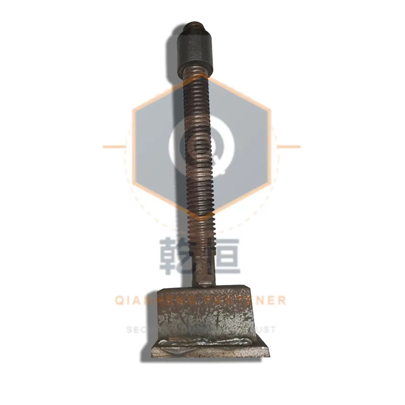
The photograph shows the feature that drives the entire specification, namely the visible series of pin holes running down the exposed inner tube. The spacing of those holes, and where the topmost usable hole sits relative to the top of the outer tube, is the minimum overlap made directly visible, and a buyer can verify it on site within seconds, which is why it belongs on the delivery inspection sheet as a named check rather than as a general instruction.
Standard basis: EN 13163
4. The base plate carries both the vertical and the horizontal demand.
A prop transfers two entirely distinct loads into the founding ground, and the base plate has to handle both of them simultaneously. The vertical load is straightforward enough: concrete, falsework beams, formwork and the fixing crew all accumulate, and the plate distributes that accumulated weight over sufficient area to keep the bearing pressure within what the founding ground will tolerate.
The horizontal load is exactly where base plates are most commonly under-specified, because a slab soffit does not stand in isolation. Three separate actions push that falsework sideways, and none of them is optional. The slab edge applies a lateral pressure that tries to move the soffit outward. The falsework is not a braced frame unless someone adds the bracing. And placing the concrete produces a horizontal component that never appears in the static calculation at all. The reaction to that horizontal demand has to be developed at the base of the prop. A base plate with adequate bearing area but no shear geometry will allow the prop to slide at the bottom while the top stays put, which bends the inner tube in a way it was never certified for. A plate with a good shear key but a small footprint will punch into soft ground, tilt the bay and change the effective soffit height.
Procurement should therefore specify the plate as four separate attributes rather than as a single plate, and all four of them have to be stated explicitly. The plate diameter sets the bearing area under the vertical load, while the plate thickness sets its stiffness under the bending moment. The number and spacing of the fixing holes determine whether the prop can be tied to a sole board or a pad. The shear geometry determines whether it resists a horizontal push without sliding at the base. This is also the point at which the tie hardware intersects with the falsework itself. The plate fixing holes and the square base plate and washer arrangement serve different purposes, yet they are frequently ordered in one package. A buyer who lumps them together tends to receive a plate with the wrong hole pattern for either job.
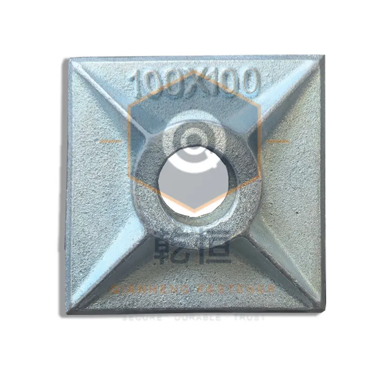
What to look for on this component is specific rather than general. The bearing face should be flat and continuous, with no weld spatter interrupting it, because a spatter bead under the plate becomes a high spot that rocks the prop and concentrates the load onto one edge of the base. The weld between the plate and the tube should be continuous on at least two opposite sides, because a fillet weld on one side only leaves the plate free to rotate under a bending moment. And the fixing holes should be symmetric about the tube axis, since an asymmetric pattern lets the prop be installed offset from the load line without anyone noticing. None of those details is expensive to specify, and all three remain cheap to verify on site.
5. Pin and bolt, wedge, or collar, and what each one tolerates.
Which lock design should a buyer actually choose? It depends entirely on the lateral load rather than on the fixing crew's preference, and the three common designs fail differently enough that the choice belongs in the specification rather than in the price comparison.
A pin and bolt design passes a pin through a matched hole in the inner tube and secures it with a bolt through the corresponding hole in the outer tube. It is positive and it does not creep, but it depends entirely on the holes being correctly matched and on the pin not being a loose fit in service. A worn pin hole is a common reason a prop is rejected on inspection, and a worn hole does not fail safely — it allows a small amount of slip that becomes a measurable drop in effective height under load.
A wedge design uses a wedge-shaped locking piece that draws the two tubes together and jams them by friction. It is fast to operate and genuinely quick to adjust, which is why it is popular on repeatedly adjusted falsework. What it cannot do is tolerate any lateral movement without gradually walking out. A wedge lock under a horizontally loaded prop will work loose, and the adjustment speed is exactly what makes it unsuitable on a prop that sees sustained lateral load.
A collar design instead rotates the inner tube so as to engage internal threads in the outer tube. It is the most positive of the three and it will not walk, but it costs more and adjusts more slowly, which is why it appears on permanent shoring and re-shoring rather than on high-cycle slab falsework.
For a procurement engineer the practical rule is that the lock selection should follow the lateral load, not the fixing crew's preference. A prop under a slab edge that is taking sustained outward pressure needs a positive lock. A prop in the middle of a bay taking no lateral load can be a wedge. And a prop that will be used for re-shoring after a pour has struck should be a collar, because it will stay in place unattended for days. The timing question on that last point belongs with the striking sequence and crew hours programme rather than with the purchase order itself.
Standard basis: EN 12812
6. Inspection at delivery, by defect rate rather than by sample.
How should a shoring lot actually be inspected? A shoring lot is a large population of single-value items, which makes it behave like a production batch rather than a consignment of interchangeable components. A prop leg either locks properly or it does not, and a production lot tends to be good or bad in that respect as an entire batch. Sampling a small number of units and accepting the remainder is simply the wrong inspection instrument for that particular kind of distribution.
Any delivery inspection of a shoring consignment should be structured in two distinct passes. The first is a sight check on every prop as it comes off the truck, examining the defects that are visible, and any prop failing that pass is out rather than into a pending pile.
The defects that reject a prop on sight are worth listing explicitly, because crews and inspectors tend to judge by eye and unaided eye is unreliable across a shoring lot of this size:
- A bent or kinked outer tube, visible as a curve where the tube should be straight.
- A dented or ovalised lower section, often caused by dropping rather than by transport.
- A deformed or elongated pin hole, which allows the inner tube to slip under load.
- A head plate hammered flat or split at the edge.
- A missing, mismatched or substituted pin and bolt set.
- A locking device that operates stiffly, or one that engages without the pin fully passing the hole.
- A base plate with a cracked fillet weld or a deformed hole pattern.
- A load class stamp that is missing, illegible or inconsistent with the delivery documentation.
The second pass is a percentage check on the balance of the consignment, and its purpose is to verify the three numbers actually specified. Take ten per cent at random, spread them, and confirm the extension range against the marking, confirm the lock engages at every claimed position within the working range, and confirm that the load class stamp is both present and legible. The purpose of the second pass is not to re-test the lot but to detect a consignment that is not the product ordered, which is precisely the failure a first-pass visual inspection cannot reveal. It is the same logic as the delivery inspection applied to a shoring component, and it also protects the acceptance record if the lot is later involved in a structural question.
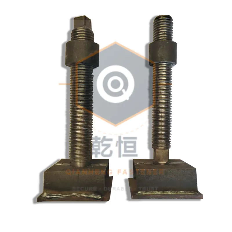
7. Worked example: a 600 square metre slab bay set.
Consider a slab bay of 600 square metres at a soffit height of 3.2 m, poured in a single lift, carrying a soffit of timber secondary beams spanning onto H20 primary beams.
A first pass at the quantity divides the slab area by a nominal prop bearing area of roughly 0.36 square metres and arrives at a comfortable round figure of 1,700 props. That number is wrong in one very specific way, and the manner of its failure is worth tracing precisely because it is the same error repeated on every comparable job.
The prop leg required here has an extension range that comfortably covers 3.2 m of soffit to the underside of the supporting beams. But once the minimum overlap is respected, and once the head plate and sole board thicknesses are added into the stack height, the usable range narrows. If the specified working range turns out to be 2.4 m to 3.3 m, the prop still qualifies, and 1,700 remains defensible. If the specified working range proves to be 2.9 m to 3.4 m, then this prop cannot be used at all at a 3.2 m soffit, and the correct action is a post-shore or a different prop. The quantity calculation alone cannot tell you which of those two outcomes actually applies, because the answer lives in the prop leg specification rather than in the slab geometry.
In that configuration the quantity, the acceptance rate and the rejection criteria all derive from the same three governing numbers, which is exactly what makes a shoring lot a specification problem rather than a simple counting problem. It is also why a supplier who quotes a prop leg by reach alone has not quoted the same article as one who quotes a class, an overlap and a plate.
8. What to put in the purchase order.
A prop leg order that survives production needs the following stated explicitly, and each of these is a measurable value a supplier can afterwards be held to.
The extension range has to be stated as a working range rather than a total reach, because total reach includes those sections where the minimum overlap is simply not available. The minimum overlap must be stated in millimetres at the topmost usable hole, and the load class named together with its test standard, with the capacity figure required at the extension the job actually uses rather than at the class maximum. The locking type is stated as pin and bolt, wedge or collar, and the base plate as diameter, thickness, fixing hole count and spacing, and shear geometry. The pin hole pitch and count matters because it determines the setting range actually available, while the quantity split by extension band matters because a lot is rarely all one size on a job with more than one soffit height. Finally the incoming inspection provision needs to be stated, including precisely what constitutes rejection.
That list is long, and it is long because a prop leg is a structural component being bought by part number. Procurement engineers who shorten the list by accepting a catalogue reference have saved no procurement time; they have simply relocated the decision into an acceptance inspection that will be argued rather than measured. The like-for-like quotation comparison approach applies with unusual force here, because two suppliers quoting "D15 adjustable prop" are quoting only a reach, and a reach by itself is not a product.
9. Where steel shoring stops being the right answer.
Steel falsework is the wrong answer in three recognizable situations, and identifying them early in the design is considerably cheaper than discovering them at the erection stage.
The first is a soffit height beyond the certified working range of the prop being supplied. This is fundamentally a range problem rather than a strength problem, and it cannot be solved by buying a heavier prop leg, because a heavier class still carries its own maximum extension. The correct answers are a post-shore left in place after striking, a telescopic steel shore with a substantially greater range, or a proprietary branded system. The decision is a scheduling decision as much as a technical one, because it determines how long anything stays under the slab.
The second is a repeating high-cycle operation where the same volume of concrete is poured many times in the same footprint. In that situation the economics of a labour-intensive falsework built and dismantled each cycle are poor, and an aluminium or table form becomes competitive on total installed cost even at a higher purchase price. That comparison has to be made on installed cost per cycle rather than on purchase price alone, and it also has to include the handling and storage logistics that any repeatedly deployed system necessarily requires.
The third is a form so complex that the number of distinct prop lengths and head positions exceeds what a crew can set accurately from a drawing. At that point the falsework becomes a bespoke assembly, and bespoke assemblies are precisely where falsework failures tend to concentrate. The alternative is a panelised approach, and the panel layout and bill of materials method provides the right structure for making that call.
The common thread across all three is that the prop leg is being asked to solve a problem it was not designed for. It is a compression strut with a variable length and a positive lock, and it is extremely good at exactly that. The why formwork fasteners fail analysis applies to shoring as much as to hardware, and the most common cause in both cases is a component asked to do something outside its specified envelope.
A shoring specification is worth having checked before the order is placed, and our engineering desk reviews prop leg and falsework packages against the geometry you send. If you would like that review, or if you want the purchase order wording reviewed against a drawing you already hold, ask the engineering team or read how we work. This article was reviewed by the Qianheng Formwork Engineering team against the reference configuration quoted in section 7.
References and standards.
- EN 13670 — Execution of concrete structures
- ACI 347 — Guide to formwork for concrete
- OSHA 1926.703 — Concrete equipment and formwork
- OSHA concrete safety and health topics
- ISO 2859-1 — Sampling procedures for inspection by attributes
- ISO 9001:2015 — Quality management systems
About us: This article covers how extension, overlap, and base plates affect the performance of adjustable steel prop legs. Our manufacturing process is ISO 9001 certified. Our contact page provides direct access to our technical support team, and the about page documents our company history and capabilities. This article was reviewed by the Qianheng Formwork Engineering team.