
Tie rod selection is often done backwards. A layout is inherited from the previous job, a rod size is chosen to match it, and the calculation is reconstructed afterwards to justify a decision already made. Reversing that order costs about ten minutes and removes most of the risk.
Step 1 - Establish the lateral pressure
Lateral pressure is generated by the fluid concrete before it stiffens, and it never exceeds full hydrostatic pressure. A first, safe estimate is therefore the full hydrostatic value for the height of the lift: density multiplied by height. Taking 25 kN/m3 for normal reinforced concrete, a 3 m lift gives 75 kPa at the base. Real pressure is lower because concrete stiffens as it is placed, and lower still when the pour is slow or the concrete is warm, but the hydrostatic figure is the conservative ceiling and it is the right number to start from.
Step 2 - Load carried by one tie
Each tie supports the pressure acting on the tributary area it serves, which for a regular grid is simply the horizontal spacing multiplied by the vertical spacing. Lay that against pressure and the load per tie appears directly.
| Pressure at base | Tie spacing 0.8 x 0.8 m | Spacing 1.0 x 1.0 m | Spacing 1.2 x 1.2 m |
|---|---|---|---|
| 50 kPa | 32 kN | 50 kN | 72 kN |
| 75 kPa | 48 kN | 75 kN | 108 kN |
| 100 kPa | 64 kN | 100 kN | 144 kN |
Step 3 - Compare with the allowable load of the rod
The calculated load must be compared with the permissible working load of the assembly, and this is where most procurement errors occur. Datasheets are quoted in different terms: some publish a yield load, others a permissible load already divided by a factor. If the figure is a yield load, divide it by the project safety factor before comparing. As an indication, a D15 system is commonly rated around 150 kN and a D20 around 230 kN in yield terms, which is why D20 is chosen for high lifts and heavy pour rates rather than for convenience.
Step 4 - The checks that are easily missed
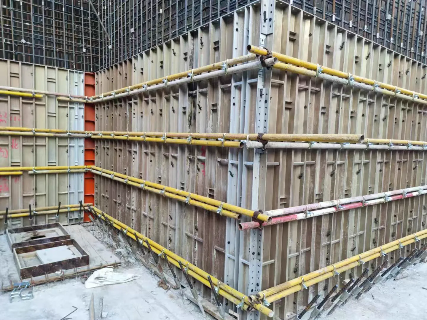
- The cone, the embedded anchor or the washer plate, not the rod, is frequently the governing element.
- Spacing is measured between ties as installed; a misplaced tie enlarges the tributary area of its neighbours.
- At the edge and at corners the tributary area is not halved by symmetry, it is truncated, so pressure finds fewer ties than the grid suggests.
- Ties in the lower zone carry more pressure per tie when spacing is constant, so a uniform grid is never uniformly loaded.
What to state in the RFQ
Give the supplier the four inputs, not just a part number: height of the lift, pour rate, concrete temperature at placement, and the intended tie spacing. With those, capacity can be confirmed against the actual duty rather than against a catalogue page, and any mismatch between the rod and the rest of the assembly is caught before the pour rather than during it.