
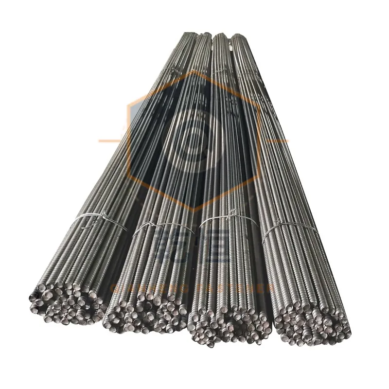
D12 is the most common small tie rod in formwork, and the one most often used outside its envelope. It is nominally a 12 mm thread, about 0.74 kg/m, normally supplied between 200 mm and 6000 mm, and used with a 100 mm disc nut. It is cheap, light and universal, which is why it ends up on thin walls, infill panels, secondary structure and temporary works. The same universality is the problem: it is applied to 300 mm shear walls at high pour rates, its 35 kN and 50 kN figures get copied into calculation sheets as design values, and ordinary 60° threaded bar is substituted for the trapezoidal thread without a second thought.
This article works the whole chain — thread geometry, section reduction, steel grade, the difference between a guaranteed capacity and an allowable load, locking hardware fit, and a selection method driven by wall thickness and pour rate. Every formula states its symbols and units, and each worked example carries its intermediate results so you can check it on a calculator.
What this guide settles
Take the conclusion first. D12 is a low-capacity, low-weight, highly versatile tie rod. It is the right choice when the load per rod stays comfortably below 25.0 kN in 45# steel or 17.5 kN in Q235. Once the calculated rod load approaches or exceeds that, densifying the spacing is usually more expensive than stepping up to D15.
The numbers behind that statement are these. A 45# D12 has a guaranteed capacity of about 50 kN; divided by a safety factor of 2.0 that gives an allowable design load of 25.0 kN. The Q235 version gives about 35 kN and 17.5 kN respectively. Those two figures are the ceiling on what a D12 can do.
Converted into wall area: on a normal shear wall poured at 2 m/h with concrete at 20 °C, design lateral pressure is about 68 kN/m². A 45# D12 can then carry 25.0 ÷ 68.0 = 0.368 m², roughly a 500 × 700 mm grid. A Q235 D12 carries 0.257 m², roughly 500 × 500 mm. Those areas are the physical limit of the product.
There is also an economic limit. On site, tie spacing below 500 × 500 mm (0.30 m² tributary area) is already dense, because reducing spacing multiplies locking hardware, waler rows and installation labour, none of which shrink when the rod gets smaller. So a simple criterion follows: 45# D12 stays economic up to a design pressure of about 83 kN/m², and Q235 D12 up to about 58 kN/m². Both thresholds are verified against worked examples later in this article.
One more sentence belongs at the front, because it decides whether a D12 is used correctly at all: 35 kN and 50 kN are guaranteed capacities, not allowable design loads. They correspond to the section reaching the lower bound of the material's tensile strength — close to the point of fracture. Design must divide by a safety factor on top. Treating a guaranteed value as an allowable value is equivalent to silently setting the safety factor to 1.0, and it is the most common analytical error behind D12 failures.
1. What D12 is, and why the "12" is not the bar diameter
D12 is a tie rod with a 12 mm nominal thread major diameter, rolled from cold-drawn round bar into a trapezoidal thread, with a disc nut at each end clamping the formwork and walers together against the lateral pressure of fresh concrete. It is a turnover item: stripped out, cleaned, straightened if needed, and reused.
The "12" refers to the thread major diameter, not the bar body. That distinction matters directly to the capacity calculation, as the next sections show.
How a D12 rod carries load
A D12 tie rod is a single continuous rolled thread with no intermediate coupling. Thread runs to near each end, leaving either a short plain section or a thread run-out. It passes through the aligned holes in the formwork faces, and at each end the load path runs: panel face → secondary bearer → primary waler (usually a pair of φ48 tubes) → locking hardware (100 mm disc nut) → rod end protruding 1 to 3 pitches.
Fresh concrete pressure acts on the panel first, the panel passes it to the secondary bearers, those load the double-tube waler, and the waler loads the disc nut and rod, which balance the two faces against each other. Every link in that chain is a structural element, and failure of any one shows up as a bulging form — but the root cause differs each time.
The tie rod is the only element in the chain in pure tension. Everything else bends. That difference is the key to understanding the selection logic: a bending member's stress scales with the square of its span and its deflection with the fourth power, whereas a tension member's stress scales only with the tributary area it carries. Open up the tie spacing and the waler will reach its limit before the rod does.
Why trapezoidal thread, not a standard 60° thread
Formwork tie rods use a conventional or rounded trapezoidal thread with a 30° flank angle, not the 60° of an ordinary metric thread. Four practical reasons.
A thicker thread root resists wear and stripping. A basic trapezoidal profile has a root width of about 0.366 times the pitch; an ordinary 60° thread has 0.25 times the pitch or less. At a 12 mm nominal diameter, coarse M12 has a 1.75 mm pitch and a root width near 0.44 mm, while a 3 mm pitch trapezoidal thread gives about 1.10 mm — two and a half times wider. A wider root lowers the stress concentration factor and slows the rounding of the crest under repeated assembly.
Lower radial force, so the nut can be thin. The larger the flank angle, the greater the radial component the normal force resolves into, which pushes the nut outward. A 30° flank resolves much less radially than 60°, so the nut does not need a thick wall to carry the tension. That is precisely what makes a pressed thin-walled disc nut with a large face possible.
A small lead angle, so it self-locks. Despite the coarse pitch, the thread is deep, so the lead angle stays small. Combined with concrete slurry filling the thread, the nut resists vibrating loose during compaction and pouring. This matters most on tall walls and columns.
A rounded profile is kinder to the root. A rounded trapezoidal thread keeps the 30° flank but arcs both crest and root. The larger root radius reduces notch sensitivity further — the stress concentration factor can be 20–30% lower than a sharp-cornered profile. The rounded form also lets metal flow more freely during rolling, which extends die life and leaves a smoother surface that slurry does not grip.
The drawbacks are equally clear: a coarse, deep thread has a smaller effective section than a fine 60° thread at the same nominal diameter, and rolling consumes part of the bar section. That is why a 12 mm rod has an effective section of only about 84 mm², while the 113 mm² obtained from the nominal diameter cannot be used for strength calculations.
Nominal, effective and root area
Lay the three sections of a D12 side by side and the capacity figure stops being a mystery. Take a major diameter d = 12 mm and a pitch P = 3 mm: basic thread height H1 = P/2 = 1.5 mm, with a 0.25 mm crest clearance.
Nominal area. From the major diameter, A = π × d² / 4 = π × 6² = 113.1 mm². This is the circumscribed circle. It is a dimensional description, not a strength value.
Effective area. After allowing for the thread cutting into the net section, the value used for strength calculation on a D12 is about 84 mm², equivalent to a 10.34 mm diameter.
Reduction. 84 ÷ 113.1 = 74.3%, so the thread removes more than a quarter of the section. Estimating capacity from the nominal area overstates it by about 35%, which is the most concealed of the common errors.
Why does the effective area land at 84 mm² rather than lower? Because tie rod threads are rolled, not cut. Rolling feeds cold-drawn round bar slightly under the major diameter into a thread rolling die and extrudes the profile by plastic flow: the blank is close to the pitch diameter, the crest rises as material is displaced, and the root ends up only slightly below the blank. Cutting a thread removes material from the major diameter, so the root necessarily sits at the major diameter minus twice the thread height and the section loss is much larger. Rolled threads also keep the metal flow lines continuous rather than severed, aligning the fibre direction of thread and bar, which gives better fatigue performance than a cut thread.
The 0.74 kg/m unit weight happens to corroborate the "blank near pitch diameter" conclusion. With steel at 7.85 g/cm³, round bar weighs m = 0.00617 × d² kg/m with d in mm. Inverting 0.74 kg/m gives an equivalent diameter of √(0.74 ÷ 0.00617) = √119.9 = 10.95 mm. That sits between the thread pitch diameter (10.34 mm) and the major diameter (12 mm), which is exactly the geometry rolling produces. The engineering consequence: the bar body of a D12 is of the order of φ11 mm, and 12 mm is the thread major diameter, not the bar. Estimating weight as 0.00617 × 12² = 0.889 kg/m overshoots by 20%, and freight and cost take-offs drift with it.
One word of caution on units of comparison. The published unit weights of D15 and D20 (1.39 kg/m and 2.47 kg/m) coincide exactly with the nominal-diameter formula (0.00617 × 15² = 1.39 and 0.00617 × 20² = 2.47), whereas the D12 figure of 0.74 kg/m corresponds to a 10.95 mm equivalent diameter. Unit weight may be quoted on the thread major diameter for one size and on the actual bar section for another. Do not extrapolate across sizes with a single formula; use a measured weight on delivery or the supplier's declared figure. Capacity is independent of rod length and has no functional relationship with unit weight, and the two cannot be substituted for each other.
2. D12 at a glance
The table below collects the governing parameters. The capacity rows are guaranteed capacities — characteristic values, not allowable design loads. Design must divide by a safety factor; the conversion and its basis are in section 4.
| Parameter | Value / specification | Notes |
|---|---|---|
| Size designation | D12 | 12 mm thread major diameter |
| Thread form | Conventional or rounded trapezoidal | 30° flank angle; thicker root, better load and wear behaviour than a 60° thread |
| Common pitch | 3 mm | Basic root width about 1.10 mm |
| Steel grade | Q235 carbon structural steel / 45# quality carbon steel | To GB/T 700 and GB/T 699 respectively; nearest international counterparts are ASTM A36 or EN S235JR for Q235, and AISI 1045 or EN C45E for 45# |
| Standard lengths | 200 – 6000 mm | Sized from wall thickness + formwork + walers + locking hardware + end protrusion, then rounded up |
| Unit weight | About 0.74 kg/m | Equivalent bar diameter about 10.95 mm |
| Thread major diameter d | 12 mm | The source of the "12" |
| Nominal area | 113.1 mm² | π × 6²; dimensional only, never used for strength |
| Effective thread area A_s | About 84 mm² | The value used for strength; equivalent diameter 10.34 mm |
| Guaranteed capacity, Q235 | About 35 kN | Characteristic value, corresponding to about 417 MPa section stress |
| Guaranteed capacity, 45# | About 50 kN | Characteristic value, corresponding to about 595 MPa section stress |
| Allowable design load, Q235 (K = 2.0) | 17.5 kN | See section 4 for the more conservative 15.5 kN reading |
| Allowable design load, 45# (K = 2.0) | 25.0 kN | Design value |
| Matching locking hardware | 100 mm disc nut | About 0.425 kg each |
| Surface finish | Blue-white (clear) or yellow (iridescent) zinc plating | Zinc layer in the 5–12 μm range; see section 5 |
| Recommended final torque | 25 – 40 N·m | Not to exceed 50 N·m; see section 8 |
Two rows on that table are misread most often. The first is the length range: 200 mm covers very thin members such as 100 mm partitions, upstands and trim, while 6000 mm covers very thick members or special propping. Neither extreme is common; the bulk of usage sits between 500 mm and 1200 mm. The second is the pair of capacity rows: neither depends on length. A 300 mm D12 and a 6000 mm D12 of the same steel and thread carry exactly the same tension. Length affects weight and handling only.
Length and weight scale linearly, which turns 0.74 kg/m into a working tool. The table below converts it for take-off and lifting.
| Length (mm) | Weight per rod (kg) | Weight per 1000 rods (kg) | Typical wall thickness (mm) |
|---|---|---|---|
| 200 | 0.148 | 148 | About 40 and under (upstands, trim, tie-in details) |
| 300 | 0.222 | 222 | About 100 |
| 400 | 0.296 | 296 | About 100 – 150 |
| 500 | 0.370 | 370 | About 200 |
| 600 | 0.444 | 444 | About 300 |
| 700 | 0.518 | 518 | About 400 |
| 800 | 0.592 | 592 | About 500 |
| 1000 | 0.740 | 740 | About 700 |
| 1200 | 0.888 | 888 | About 900 |
| 1500 | 1.110 | 1110 | About 1200 |
| 2000 | 1.480 | 1480 | About 1700 |
| 3000 | 2.220 | 2220 | About 2700 |
| 4000 | 2.960 | 2960 | About 3700 |
| 5000 | 3.700 | 3700 | About 4700 |
| 6000 | 4.440 | 4440 | About 5700 |
Three calculations are worth memorising on the back of that table. One, converting weight to length: one tonne of D12 rod is roughly 1000 ÷ 0.74 = 1351 m, so ten tonnes is about 13 514 m — the freight and stock basis. Two, estimating a bundle: a 600 mm D12 weighs 0.444 kg, so 1000 rods come to 444 kg, which tells you at a glance whether two people can move the bundle. Three, verifying a take-off: wall area times rods per square metre times weight per rod gives total rod weight, as worked through in section 7. The longest row, 6000 mm at 4.44 kg per rod, needs dedicated racking and lifting gear.
3. Q235 against 45# — which steel, and when
The difference between Q235 and 45# is not "adequate" against "better". It is a trade between strength on one side and ductility and workability on the other. The 45# rod is about 43% stronger (50 kN against 35 kN guaranteed) but carries more than twice the carbon, which costs plasticity, toughness and weldability, and costs more to buy. The choice is a calculation, not a preference.
Chemistry and mechanical properties
| Item | Q235 (GB/T 700) | 45# (GB/T 699) |
|---|---|---|
| Steel class | Carbon structural steel | Quality carbon structural steel |
| Carbon content | Not over 0.22% (Q235B about 0.12 – 0.20%) | 0.42 – 0.50% |
| Manganese content | 0.30 – 0.70% | 0.50 – 0.80% |
| Yield strength ReL | Not below 235 MPa | Not below 355 MPa |
| Tensile strength Rm | 370 – 500 MPa | Not below 600 MPa |
| D12 guaranteed capacity | About 35 kN | About 50 kN |
| Corresponding section stress (A_s = 84 mm²) | About 417 MPa | About 595 MPa |
| Elongation after fracture A | Not below 26% | Not below 16% |
| Yield-to-tensile ratio | About 0.50 – 0.60 | About 0.59 |
| Impact toughness at 20 °C | Not below 27 J (grade B) | Around 30 J in normalised condition, clearly lower relative to Q235 |
| Hardness reference | About HB 110 – 130 | About HB 170 – 200 (hot rolled, normalised) |
| Weldability | Good, standard procedures | Poor; preheat 150 – 200 °C and slow cooling, prone to hardening cracks |
| Cold formability | Excellent, easy to roll | Moderate; rolling force and die life need control |
| Relative material cost | Baseline | About 1.2 – 1.5 times baseline |
Where the carbon difference shows up on site
Q235 caps carbon at 0.22%; 45# runs 0.42 to 0.50%, more than double. Carbon content is the origin of every other difference. Carbon is the main strengthening element in steel: raise it and the pearlite fraction grows, so strength and hardness rise, but ferrite falls away and plasticity and toughness drop. During welding, the heat-affected zone readily forms martensite and embrittles.
On a D12 rod this chain produces three concrete outcomes. First, a 43% strength gap: 45# gives 50 kN at about 595 MPa, Q235 gives 35 kN at about 417 MPa. Second, a ten-point ductility gap: Q235 elongates at least 26% against at least 16% for 45#. Ductility is what decides whether an overloaded rod stretches visibly before it parts. A higher elongation gives the site warning; a lower one fails more abruptly. Third, poor weldability: 45# needs preheat, interpass temperature control and slow cooling after welding, otherwise the heat-affected zone hardens sharply and cold cracks appear. The rod body itself is rarely welded, but if positioning tabs, water stop plates or extension couplings have to be welded on site, 45# is markedly harder to handle than Q235.
A further effect is easy to overlook. Steel loses toughness as temperature falls, and the loss is greater at higher carbon content. In winter construction, northern projects and low-temperature environments, a 45# rod is more exposed than Q235 to brittle fracture under impact — a swinging pump hose, a hammer blow during stripping. That is not an argument against 45# in winter; it is an argument for protecting the rod ends from impact and for banning direct hammer blows on the end face during stripping.
Choosing between them
| Criterion | Choose Q235 | Choose 45# |
|---|---|---|
| Design load per rod | Not over 15.5 kN (conservative reading) or 17.5 kN | Not over 25.0 kN |
| Design lateral pressure q_d | Not over 58 kN/m² | Not over 83 kN/m² |
| Member type | Thin walls, infill, secondary structure, small columns, upstands and trim | Normal shear walls, thick walls, tall lifts |
| Turnaround cycles | Short projects, 3 – 5 cycles | Long-life critical projects |
| Further processing | Site welding or modification required | No welding, kept as supplied |
| Ambient conditions | Low temperature, impact exposure | Normal temperature, ends protected |
| Required margin | Ordinary | High (critical members, supervised locations) |
A note on how the Q235 figure is presented, because two readings exist. This article works from the 35 kN guaranteed capacity and derives a 17.5 kN allowable load at a safety factor of 2.0. But GB/T 700 gives Q235 tensile strength as a range, 370 to 500 MPa. Rechecking independently from the lower bound gives 84 mm² × 370 MPa = 31.1 kN, which is 11% below 35 kN and yields an allowable load of only 15.5 kN. The conservative course is to take the lower figure, 15.5 kN, and treat 35 kN as an upper reference for incoming inspection. An 11% difference changes nothing on thin walls, but near a boundary it can decide whether you tighten one spacing step.
4. From guaranteed capacity to allowable load
Capacity calculation has only three steps: find the section, find the material strength, apply the safety factor. Take the effective thread area A_s of about 84 mm², the specified strength of Q235 or 45#, and a combined safety factor of 2.0 covering thread stress concentration, eccentric loading, turnover wear and material scatter. The result is the allowable load. Divide it by the design lateral pressure and you have the formwork area one rod can carry.
What 35 kN and 50 kN actually mean
Divide the guaranteed capacity back through the section and both figures become transparent. With A_s = 84 mm²:
| Steel | Guaranteed capacity (kN) | Effective area (mm²) | Section stress (MPa) | Specified tensile strength (MPa) | Reading |
|---|---|---|---|---|---|
| Q235 | 35 | 84 | 417 | 370 – 500 (GB/T 700 range) | Inside the range, 1.13 times the lower bound |
| 45# | 50 | 84 | 595 | Not below 600 (GB/T 699) | Essentially at the lower bound, fracture level |
| Q235, conservative | 31.1 | 84 | 370 | 370 (lower bound) | Exactly at the lower bound |
| 45#, section check | 50.4 | 84 | 600 | 600 (lower bound) | Exactly at the lower bound |
This is the single most important reading in the article: 35 kN and 50 kN are the loads at which the section reaches the specified tensile strength — the point beyond which it breaks. The 45# figure of 595 MPa is within 1% of the 600 MPa lower bound. The Q235 figure of 417 MPa sits low-middle in its range. Neither is an allowable value.
If you compute stress from the nominal area of 113.1 mm² instead, you get 50 ÷ 113.1 = 442 MPa and 35 ÷ 113.1 = 309 MPa, which understates the true stress by 26% to 35%. That understatement makes a designer believe there is room to open the spacing or drop a size. Run in the opposite direction, it produces claims like "a D12 carries 113.1 × 600 = 67.9 kN", which is badly overstated. Effective and nominal areas are different quantities, and only the first belongs in a capacity calculation.
Three different "capacities" — do not mix them
The word capacity carries three distinct meanings in practice, and mixing them is the principal source of design error.
| Definition | Meaning | D12 in 45# | Use |
|---|---|---|---|
| Guaranteed load (proof load) | Section capacity at the specified tensile strength; near fracture | About 50 kN | Upper reference for acceptance and incoming verification |
| Yield load | Load at which the section reaches yield strength and permanent extension begins | 84 × 355 ÷ 1000 ≈ 29.8 kN | Establishing whether irreversible deformation has occurred |
| Allowable design load | Guaranteed load divided by the combined safety factor; must not be exceeded | 50 ÷ 2.0 = 25.0 kN | Formwork design and checking |
One detail deserves attention. The yield load of a 45# D12 is about 29.8 kN while the allowable design load is 25.0 kN — a ratio of 1.19. Designing at a safety factor of 2.0 therefore places the rod only 19% below yield: still elastic, but without much room. Drop the safety factor to 1.5 and the allowable load becomes 33.3 kN, which exceeds the 29.8 kN yield load. The rod could then take permanent extension under design load, arriving on the next cycle stretched, with a changed pitch and a nut that will not run back on. That is why 2.0 is recommended as the norm and 1.5 the floor: the safety factor is not only there to prevent rupture, it is there to keep the rod elastic and reusable.
Incoming verification must use criteria that match the definition. In destructive tensile testing, measured capacity should not fall below the value computed from the lower bound of the specified strength: 84 × 600 ÷ 1000 = 50.4 kN for 45#, and 84 × 370 ÷ 1000 = 31.1 kN for Q235. In non-destructive testing, load to 1.5 times the allowable design load — 37.5 kN for 45# — hold for two minutes, and check three things: no yield extension, no thread slip, no relative movement of the nut.
Choosing a safety factor
The factor is not a matter of taste. It has to cover five classes of uncertainty, each of which can be quantified.
| Source of uncertainty | Effect on capacity | Order of magnitude | Comment |
|---|---|---|---|
| Thread stress concentration | Reduces | 10 – 20% | Peak stress at the root exceeds mean stress; a rounded profile mitigates it |
| Eccentric loading | Reduces | 5 – 15% | Nut face not seating on the waler, rod not concentric with the hole |
| Turnover wear and corrosion | Reduces | 10 – 20% | Worn crests and corroded threads shrink the effective section |
| Material strength scatter | Both ways | 5 – 10% | Tensile strength varies within a heat |
| Lateral pressure estimate error | Both ways | 10 – 30% | Pour rate, placing temperature and setting time assumptions |
| Combined requirement | — | Not less than 1.5; conventionally 2.0 | At 2.0 the rod remains elastic under design load |
Practical guidance: take K = 2.0 as the norm, which is both the safest and the most widely accepted course. Relax to K = 1.5 only where a third-party material certificate exists, the rods are new and unused, and the loads are well characterised with measured pressure parameters. For rods past five turnover cycles, or with visibly worn or corroded threads, apply a further 0.85 factor on top of K = 2.0, which reduces the allowable load from 25.0 kN to 21.3 kN. Under no circumstances take K below 1.5.
Worked example A: a 200 mm infill wall
The first example runs the whole chain with every intermediate result stated. Case: a 200 mm non-load-bearing infill wall, 3.0 m high, 45# D12 rods.
Setting time: placing temperature T = 25 °C, so t0 = 200 / (T + 15) = 200 / 40 = 5.00 h.
Pressure from the formula: with γc = 24 kN/m³, a 160 mm slump giving β = 1.0, and a pour rate V = 1.5 m/h, F1 = 0.28 × 24 × 5.00 × 1.0 × √1.5 = 33.60 × 1.2247 = 41.2 kN/m².
Hydrostatic value: F2 = γc × H = 24 × 3.0 = 72.0 kN/m².
Take the lower: F = min(41.2, 72.0) = 41.2 kN/m², governed by the formula.
Effective head: h = F ÷ γc = 41.2 ÷ 24 = 1.71 m. The lowest 3.0 − 1.71 = 1.29 m of the wall is at full pressure, so the bottom two rows of rods carry equal and maximum load.
Design pressure: with chute and tremie placing, Q2 = 2.0 kN/m², so q_d = 1.2 × 41.2 + 1.4 × 2.0 = 49.44 + 2.80 = 52.2 kN/m².
First spacing trial: horizontal a = 500 mm and vertical b = 500 mm, tributary area A = 500 × 500 × 10⁻⁶ = 0.25 m².
Rod load: characteristic N_k = 41.2 × 0.25 = 10.3 kN; design N_d = 52.2 × 0.25 = 13.0 kN.
Allowable load for 45# D12: 50 kN ÷ 2.0 gives [N] = 25.0 kN. Checked independently by the section method, 84 mm² × 600 MPa ÷ 2000 = 25.2 kN — under 1% apart.
Verification: 13.0 ÷ 25.0 = 52%. Pass, with comfortable margin.
The same wall in Q235: [N] = 35 ÷ 2.0 = 17.5 kN, giving 13.0 ÷ 17.5 = 74.3%. A pass, but with little room. Held at 500 × 500 mm the Q235 rod remains just workable; to bring utilisation down to about 60%, tighten the vertical spacing to 400 mm, which gives A = 0.20 m², N_d = 10.4 kN and 59.7%. On the conservative reading, [N] = 15.5 kN, the 500 × 500 mm grid reaches 83.9%, close enough to the limit that densifying is mandatory.
Rod length: L = wall + 2 × panel + 2 × waler + locking hardware + end protrusion = 200 + 2 × 15 + 2 × 48 + 50 + 100 = 476 mm, rounded up to 500 mm.
Steel consumption: rods per square metre n = 10⁶ ÷ (500 × 500) = 4.00; rod weight = 4.00 × 0.5 × 0.74 = 1.48 kg/m²; disc nuts = 4.00 × 2 = 8.00 per m², weighing 8.00 × 0.425 = 3.40 kg/m²; combined 4.88 kg/m².
| Check | Result | Allowable | Utilisation | Verdict |
|---|---|---|---|---|
| Characteristic pressure F | 41.2 kN/m² | — | — | Governed by the formula value |
| Design pressure q_d | 52.2 kN/m² | — | — | Includes 2.8 kN/m² placing load |
| D12 / 45#, 500 × 500 | 13.0 kN | 25.0 kN | 52% | Pass, ample margin |
| D12 / Q235, 500 × 500 | 13.0 kN | 17.5 kN | 74% | Pass, margin thin |
| D12 / Q235, 500 × 400 | 10.4 kN | 17.5 kN | 60% | Pass, recommended |
Conclusion: on a 200 mm infill wall 3.0 m high, placed at 25 °C and poured at 1.5 m/h, a D12 is entirely adequate — 45# at 500 × 500 mm, Q235 at 500 × 400 mm. The design pressure of 52.2 kN/m² sits well below both economic thresholds, 83 kN/m² for 45# and 58 kN/m² for Q235, so this is D12 territory.
The steel-consumption step carries a fact that is easy to miss: in this scheme the disc nuts weigh 3.40 kg/m² against 1.48 kg/m² for the rods, so the locking hardware is 2.3 times the rod weight and 70% of the fitting total. Hardware count rises in direct proportion to rod count, and every rod takes two nuts, so densifying the grid amplifies hardware and labour more than it amplifies rod consumption. That is the basis for judging when to step up a size instead of tightening the spacing.
Note on the pressure expression. The formula F1 = 0.28 γc t0 β √V with t0 = 200/(T + 15) is the Chinese code form (GB 50666 Annex A). The physical model behind it is the same one used by ACI 347 and DIN 18218: pressure rises linearly with depth until the lower concrete starts to set, then the curve flattens, and the governing variables are unit weight, pour rate, placing temperature and consistency. If your project is designed to ACI 347 or DIN 18218, take the design pressure from that code's chart or expression at your pour rate and temperature and enter the chain at the tributary-area step; everything downstream — rod load, allowable load, spacing — is unchanged. The examples here use the GB expression because it is the design basis behind the manufacturer's test data and because it allows every intermediate value to be verified by hand.
5. The 100 mm disc nut and what it bears on
D12 is supplied with a 100 mm disc nut weighing about 0.425 kg, in blue-white or yellow zinc. The 100 mm diameter has two hard justifications: it has to span the outer faces of a double-tube waler, and it has to bring the bearing stress under the nut face down to what the waler material can take. The 0.425 kg matters because locking hardware is more than half the total fitting weight, which decides freight and cost.
Why 100 mm
The first justification is geometric. The rod passes between the two φ48 tubes of the double waler, and the nut face has to bear on both at once. If it does not, the rod simply forces the pair apart and slips between them, and the waler immediately loses its restraint. Two φ48 tubes side by side measure 48 + 48 = 96 mm across their outer faces; add assembly clearance and any local protrusion from welds or couplers, and the width to be spanned comes to about 100 mm. Below 96 mm the face either bears on one tube only or jams in the gap; well above 100 mm wastes material, adds weight and may foul the adjacent rod. A hundred millimetres is the smallest economic size that spans the pair.
The second justification is bearing stress. The nut face spreads the rod's concentrated tension into the waler, with mean stress under the face given by p = N ÷ A_disc, where A_disc = π × 50² = 7854 mm². The table gives the resulting stress for each nut size and rod class.
| Locking hardware | Bearing area (mm²) | Stress at 17.5 kN (D12/Q235) | Stress at 25.0 kN (D12/45#) | Stress at 40.5 kN (D15/45#) |
|---|---|---|---|---|
| 100 mm disc nut | 7854 | 2.23 MPa | 3.18 MPa | 5.16 MPa |
| 80 mm disc nut | 5027 | 3.48 MPa | 4.97 MPa | 8.06 MPa |
| 60 mm small disc nut | 2827 | 6.19 MPa | 8.84 MPa | 14.33 MPa |
| Plain washer, φ30 class | About 707 | 24.8 MPa | 35.4 MPa | 57.3 MPa |
| Square base plate 100 × 100 × 6 (with disc nut) | 10 000 | 1.75 MPa | 2.50 MPa | 4.05 MPa |
Read that table in two cases. Bearing on a steel tube waler, local capacity is far above every value listed, so even a 60 mm face will not crush the tube and the 100 mm dimension is doing essentially a geometric job. Bearing on a timber waler is a different matter: the design compressive strength of common softwood and fir perpendicular to grain is only about 2.5 to 2.9 MPa, and local bearing allowances do not raise it much. Now the D12/45# value of 3.18 MPa is already at the limit, and D15 at 5.16 MPa is clearly over. The correct detail is a 100 × 100 × 6 mm square base plate between the disc nut and the timber, widening the bearing area from 7854 mm² to 10 000 mm² and dropping the stress to 2.50 MPa, back inside the limit. A disc nut bearing directly on a timber waler is a common cause of crushed depressions in the timber and consequent local bulging of the formwork.
What 0.425 kg does to a take-off
The 0.425 kg figure looks unremarkable until it enters a quantity calculation. Every rod takes a disc nut at each end, so each rod corresponds to 0.85 kg of locking hardware. At 500 × 500 mm spacing that is 4.00 rods per square metre, or 4.00 × 0.85 = 3.40 kg/m² of hardware, against only 1.48 kg/m² of rod. Hardware weighs 2.3 times the rod.
| Spacing (mm) | Rods per m² | Rod weight (kg/m², L = 500 mm) | Disc nut weight (kg/m²) | Fitting total (kg/m²) | Hardware share |
|---|---|---|---|---|---|
| 400 × 400 | 6.25 | 2.31 | 5.31 | 7.62 | 70% |
| 500 × 500 | 4.00 | 1.48 | 3.40 | 4.88 | 70% |
| 500 × 600 | 3.33 | 1.23 | 2.83 | 4.06 | 70% |
| 600 × 600 | 2.78 | 1.03 | 2.36 | 3.39 | 70% |
| 600 × 800 | 2.08 | 0.77 | 1.77 | 2.54 | 70% |
Two conclusions follow. First, locking hardware holds a steady 70% of the fitting total, so estimating freight and cost from rod quantity alone understates them badly. Second, opening the spacing simultaneously reduces rod count, nut count, waler rows and installation labour — four items falling together. Spacing therefore influences cost far more than rod size does, which is why the economic boundary in section 7 is set at a 500 × 500 mm grid.
Blue-white against yellow zinc
Rods and nuts can be supplied with blue-white (clear, blue-tinted) passivation or yellow (iridescent) passivation. Both start as electroplated zinc; the difference is the passivation film.
| Item | Blue-white (clear) passivation | Yellow (iridescent) passivation |
|---|---|---|
| Process | Electroplated zinc + blue-white passivation | Electroplated zinc + coloured passivation |
| Appearance | Silver-white with a blue cast, uniform | Yellow-green to gold with a rainbow sheen, colour shifts with angle |
| Zinc thickness | Typically 5 – 12 μm (around 8 μm in practice) | Typically 5 – 12 μm plus the passivation film |
| Neutral salt spray to white rust | About 24 – 72 hours | About 48 – 120 hours |
| Corrosion performance | Moderate | Better, about 1.5 – 2 times blue-white |
| Effect on thread fit | Zinc adds roughly 10 – 20 μm across the diameter; negligible | Slightly thicker film; new nuts feel stiffer on first assembly, which is normal |
| Hydrogen embrittlement risk | High-strength parts require de-embrittlement baking | Same requirement |
| Suitable environment | Dry indoor structures, architectural concrete needing a silver finish, short turnaround | Basements, coastal and humid sites, long-life critical projects |
| Relative cost | Baseline | Somewhat higher (passivation chemistry and processing) |
The choice is straightforward: many turnover cycles, wet environment, rods moving between projects — take yellow zinc. A silver appearance required, few cycles, dry environment — take blue-white. Architectural concrete deserves particular care. If a corroded disc nut face leaves a rust mark against the formwork face, that mark bleeds into the concrete surface and becomes a colour difference that is very hard to remedy. In such locations yellow zinc or hot-dip galvanising is the safer specification.
One further point on hydrogen embrittlement. Electroplating drives hydrogen into the steel, and the risk rises with strength and hardness. A 45# D12 at around 600 MPa is a moderate case, less exposed than grade 8.8 and above, but sound practice still requires de-embrittlement baking — a few hours at about 200 °C after plating. The field test is simple: leave the plated parts for at least 24 hours before use, and if any delayed fracture appears without applied load, that is the signature of hydrogen embrittlement and the whole batch should be rejected.
Disc nuts are not the only option. Square base plates, combination nuts and double-lug disc nuts present different bearing areas and suit different pressure ranges. The principle is single: a larger face gives lower unit stress and protects the waler better, at the cost of weight and money. Higher pressure and softer waler material both argue for a larger face plus a square base plate. The standard 100 mm disc is listed on the disc nut page, with the base plate under square base plate.
6. D12 against D15 and D20
D12, D15 and D20 are three size steps in one technical family. They differ in thread major diameter, effective section, unit weight and capacity — and those four quantities are linked. Section scales with the square of diameter, capacity scales with section, and unit weight scales with the square of diameter as well. Understanding that square relationship explains why stepping up always buys more capacity than it costs in material.
| Item | D12 | D15 | D20 |
|---|---|---|---|
| Thread major diameter d (mm) | 12 | 15 | 20 |
| Thread form | Conventional / rounded trapezoidal | Conventional / rounded trapezoidal | Conventional / rounded trapezoidal |
| Nominal area π·d²/4 (mm²) | 113.1 | 176.7 | 314.2 |
| Effective thread area A_s (mm²) | About 84 | About 135 | About 245 |
| A_s relative to D12 | 1.00 | 1.61 | 2.92 |
| Unit weight (kg/m) | About 0.74 | About 1.39 | About 2.47 |
| Unit weight relative to D12 | 1.00 | 1.88 | 3.34 |
| Q235 guaranteed capacity (kN) | About 35 | About 54 | About 98 |
| 45# guaranteed capacity (kN) | About 50 | About 81 | About 147 |
| Q235 allowable load, K = 2.0 (kN) | 17.5 | 27.0 | 49.0 |
| 45# allowable load, K = 2.0 (kN) | 25.0 | 40.5 | 73.5 |
| Capacity relative to D12 (45#) | 1.00 | 1.62 | 2.94 |
| Weight per 1000 mm rod (kg) | 0.74 | 1.39 | 2.47 |
| Matching locking hardware | 100 mm disc nut | 100 mm disc nut | 100 mm disc nut + square base plate |
| Economic boundary q_d (45#, K = 2.0) | Not over 83 kN/m² | Not over 135 kN/m² | Not over 245 kN/m² |
| Typical applications | Thin walls, infill, secondary structure, small columns, temporary support, strengthening works | Normal shear walls, residential floors, 200 – 300 mm walls, tall lifts | Thick walls, bridge piers, metro side walls, high-pressure large sections |
Compare the two multiplier columns. Moving from D12 to D15 raises effective section and capacity by 1.61 and 1.62 times, while unit weight rises only 1.88 times; moving to D20 raises capacity 2.94 times against a 3.34 times weight rise. The apparent gains look similar, but the real difference lies elsewhere: stepping up raises the capacity of one rod, while densifying raises the number of rods, and those two cost very differently. A 62% gain in single-rod capacity lets you drop rod count by about 38%, since each rod covers more area; what happens to total steel then depends on the length and spacing combination, which section 7 works through.
A related warning: never mix sizes within one wall. Rods in the same pour zone restrain the same formwork, and each carries load in proportion to its tensile stiffness. A thinner rod, or one with a looser thread fit, deforms more and yields first, transferring load to its neighbours in a chain. Thread tolerances and flank angles also vary between batches and sources, so mixing leads to insufficient engaged threads on some rods. Issue rods by size, from separate racks.
7. Selection: pressure, spacing, and when to step up
Selection is not a lookup. It is a four-step chain: wall thickness, pour rate and lift height give the lateral pressure; the design pressure q_d follows; q_d times the tributary area gives the rod load; compare that with the allowable load and back-calculate the maximum spacing. The size decision happens at the end. If the back-calculated spacing has to fall below 500 × 500 mm for D12 to pass, D12 has left its economic range and the size should change.
The four-step chain
Step 1 — characteristic lateral pressure. To GB 50666 Annex A, take the lower of two expressions: F1 = 0.28 · γc · t0 · β · √V and F2 = γc · H. Here γc is the concrete unit weight in kN/m³ (24 for normal-weight concrete), t0 is the setting time in hours, computed as t0 = 200/(T + 15) when no measured value exists, with T the placing temperature in °C; β is the slump correction factor (1.0 for a 130–180 mm slump); V is the pour rate in m/h, taken as the maximum rate of rise at a single point; and H is the height from the point considered up to the pour surface, in metres.
The international equivalents express the same behaviour. ACI 347-04 uses pm = Cw · Cc · (150 + 9000 · R / T) with R the rate of rise in m/h and T the concrete temperature in °C, clamped between a minimum and the hydrostatic value. DIN 18218 gives limiting formwork pressures as a function of pour rate and consistency class, and treats self-compacting concrete close to full hydrostatic. Whichever code governs your project, the shape is the same: pressure rises with depth until setting begins, then flattens.
Step 2 — effective head and design value. The effective head h = F / γc in metres identifies which rows of rods sit in the full-pressure zone. The design pressure is q_d = 1.2F + 1.4Q2 kN/m², where Q2 is the horizontal load from placing concrete: 2.0 for chute, tremie or pump placing, 4.0 for a 0.2–0.8 m³ hopper, and 6.0 above 0.8 m³.
Step 3 — rod load. The tributary area for one rod is A = a × b × 10⁻⁶ m², with a the horizontal and b the vertical spacing in mm. The design rod load is N_d = q_d × A kN.
Step 4 — maximum spacing. The allowable tributary area is A_max = [N] / q_d m², with [N] the allowable design load. The spacing pair must satisfy a × b ≤ A_max × 10⁶ mm². Compare that with the allowable spans of waler, secondary bearer and panel, and take the smallest as the working spacing.
Where D12 fits
D12 belongs wherever the design pressure stays under 83 kN/m² in 45# or 58 kN/m² in Q235, and the spacing can be held at 500 mm or more.
| Application | Typical conditions | Why D12 fits | Watch out for |
|---|---|---|---|
| Thin walls, 100 – 150 mm | Floor height up to 3 m, pour rate up to 1.5 m/h | Low pressure, short rods, dense but individually light | Alignment of rod holes and sleeves in thin sections |
| Non-load-bearing and infill walls | Masonry infill, around structural columns | Small pour volume, naturally slow rise | Do not relax spacing control because a wall is "non-structural" |
| Secondary structure, ring beams, tie columns | Small sections, poured in stages | Pressure low, D12 capacity more than sufficient | High usage of short rods, 200 – 400 mm; count carefully |
| Small columns, pilasters | Sections up to 400 mm | Small face area, low rod load | Column clamp spacing needs a separate check |
| Temporary support, strengthening | Non-permanent, few cycles | Cheap, easy to cut and modify | Strengthening works need an independent structural review |
| Mock-up panels and first-off trials | Small trial pours | Low volume, flexible | Trial results must not be extrapolated to the main structure |
| Low-pressure locations | Hot weather (T ≥ 35 °C), slow pour (V ≤ 1 m/h) | Shorter setting time brings pressure down to about 38 kN/m² | Winter and summer parameters are not interchangeable |
| Upstands, trim, decorative elements | Height up to 500 mm | Pressure close to γc·H, very low | Short rods bend easily; check straightness |
One point deserves emphasis: "non-load-bearing" does not mean "no restraint check needed". Lateral pressure depends only on concrete unit weight, setting time, pour rate and slump. It has no direct relationship with whether the member is structural, whether it is reinforced, or what concrete grade is used. An infill wall usually rises slowly and to a limited height, but change the method to a large hopper placing in one go, or accelerate the programme with continuous pours, and the pressure exceeds any rule-of-thumb estimate. The criterion is always the calculation, never the name of the member.
Where D15 and D20 fit
| Size | Applications | Typical case | Criterion | Not suitable for |
|---|---|---|---|---|
| D15 | Normal shear walls, residential floors, 200 – 300 mm walls, tall lifts, projects with turnover requirements | q_d between 83 and 135 kN/m², or D12 needing a grid tighter than 500 × 500 mm | 40.5 kN allowable load, 62% above D12 | Thin walls around 100 mm and short-rod upstands, where D15 is simply clumsy |
| D15 | Locations where spacing must open beyond 600 mm to cut rod count and labour | Single rod allowable load 40.5 kN, 62% above D12 | 40.5 kN allowable load | Walls already governed by waler span, where the size upgrade buys little |
| D20 | Thick walls above 300 mm, basement walls, bridge piers, metro side walls, high-pressure large sections | q_d above 135 kN/m², or a pour rate over 4 m/h combined with cold weather | 73.5 kN allowable load | Residential floor construction, where D20 is plainly oversized |
| D20 | Large columns and self-compacting concrete members poured to full height in one lift | Pressure from F = γc·H reaching 100.8 kN/m² on a 4.2 m column | 73.5 kN allowable load | Low-pressure locations, where 2.47 kg/m adds freight and handling burden |
| D20 | Thick walls needing long rods above 1000 mm | High slenderness calls for greater bending stiffness against poker vibration | — | — |
One misconception is worth clearing up here: a thicker wall does not produce higher lateral pressure. Pressure is governed by pour rate, setting time, placing temperature and slump, not by wall thickness. What thickness does increase is three other things — rod length, and with it weight and cost; the stability requirement on rods under the concrete's self-weight; and the watertightness requirement. So a 500 mm wall is not automatically a D20 job, and a 150 mm wall is not automatically safe with D12. The criterion is the calculated q_d every time.
Decision table
The table is computed with γc = 24 kN/m³, T = 20 °C (rows 5 and 6 use 15 °C), β = 1.0, and chute or small hopper placing (rows 6 and 7 use a larger hopper). Recommended sizes assume 45# steel. The recommended spacing is the limit imposed by the rod itself; the working spacing must also satisfy the allowable spans of waler, secondary bearer and panel, and the smallest value governs.
| No. | Wall (mm) | Lift height H (m) | Pour rate V (m/h) | Placing temp. T (°C) | F (kN/m²) | q_d (kN/m²) | Recommended size | Recommended spacing (mm) | Rod load (kN) | Utilisation |
|---|---|---|---|---|---|---|---|---|---|---|
| 1 | 100 – 150 | 3.0 | 1.0 | 20 | 38.4 | 48.9 | D12 / 45# | 600 × 600 | 17.6 | 70% |
| 2 | 150 – 200 | 2.9 | 1.5 | 20 | 47.0 | 59.2 | D12 / 45# | 500 × 600 | 17.8 | 71% |
| 3 | 200 | 2.9 | 2.0 | 20 | 54.3 | 68.0 | D12 / 45# | 500 × 500 | 17.0 | 68% |
| 4 | 200 | 3.0 | 3.0 | 20 | 66.5 | 82.6 | D12 / 45# (at the boundary) or D15 / 45# | 500 × 500 (D12 limit) / 600 × 500 (D15) | 20.7 / 24.8 | 83% / 61% |
| 5 | 300 | 4.5 | 4.0 | 15 | 89.6 | 113.1 | D15 / 45# | 500 × 500 | 28.3 | 70% |
| 6 | 400 – 500 | 5.0 | 6.0 | 15 | 109.7 | 140.1 | D20 / 45# | 600 × 500 | 42.0 | 57% |
| 7 | Over 600 | 6.0 | By γc·H | — | 144.0 | 181.2 | D20 / 45# or grade 8.8 | 500 × 500 | 45.3 | 62% |
To use the table, locate your wall thickness, lift height, pour rate and placing temperature in the first four columns, read q_d off the seventh, then take the size and spacing. Row 4 is the watershed: q_d = 82.6 kN/m² sits against the 83 kN/m² economic boundary for 45# D12, and above it the size must change. That boundary is not an arbitrary conservative figure — it is back-calculated from the requirement that D12 spacing must not fall below 500 × 500 mm.
The next two tables show the same boundary in terms of allowable tributary area, for 45# and for Q235.
| q_d (kN/m²) | Allowable tributary area, D12/45# (m²) | Recommended spacing (mm) | Rod load (kN) | Utilisation | Verdict |
|---|---|---|---|---|---|
| 48.9 | 0.511 | 600 × 600 | 17.6 | 70% | Comfortable, spacing open |
| 59.2 | 0.422 | 500 × 600 | 17.8 | 71% | Comfortable |
| 68.0 | 0.368 | 500 × 500 | 17.0 | 68% | Typical value for a normal shear wall |
| 82.6 | 0.303 | 500 × 500 | 20.7 | 83% | Economic boundary; do not open further |
| 113.1 | 0.221 | 400 × 400 | 18.1 | 72% | Mechanically possible, but 6.25 rods/m² is uneconomic; step up |
| q_d (kN/m²) | Allowable tributary area, D12/Q235 (m²) | Recommended spacing (mm) | Rod load (kN) | Utilisation | Verdict |
|---|---|---|---|---|---|
| 48.9 | 0.358 | 500 × 600 | 14.7 | 84% | Workable, margin thin |
| 59.2 | 0.296 | 500 × 500 | 14.8 | 85% | Workable, at the Q235 economic boundary |
| 68.0 | 0.257 | 400 × 500 | 13.6 | 78% | Workable but visibly denser |
| 82.6 | 0.212 | 400 × 400 | 13.2 | 76% | Already dense; switch to 45# |
| 113.1 | 0.155 | 300 × 400 class | — | — | Uneconomic; change grade or size |
Worked example B: when D12 has to go
The second example does one thing only: run the same wall through D12 and through the next size up, and see where the difference lands.
Case: 300 mm shear wall, 4.5 m high, placed at 15 °C, poured at 4.0 m/h, 180 mm slump, 0.6 m³ hopper.
Setting time: t0 = 200 / (15 + 15) = 6.667 h, 17% longer than in example A.
Pressure: F1 = 0.28 × 24 × 6.667 × 1.0 × √4.0 = 44.80 × 2.00 = 89.6 kN/m². Hydrostatic F2 = 24 × 4.5 = 108.0 kN/m². Take F = 89.6 kN/m², which is 65% above example A. Effective head h = 89.6 / 24 = 3.73 m.
Design pressure: a 0.6 m³ hopper falls in the 0.2–0.8 m³ band, so Q2 = 4.0 kN/m² and q_d = 1.2 × 89.6 + 1.4 × 4.0 = 107.52 + 5.60 = 113.1 kN/m².
First, can D12 be forced to work? A_max = 25.0 ÷ 113.1 = 0.221 m² = 221 000 mm². Try 400 × 500 mm: A = 0.20 m², N_d = 113.1 × 0.20 = 22.6 kN, 90.5% utilisation — too tight. Try 400 × 400 mm: A = 0.16 m², N_d = 18.1 kN, 72.4% — mechanically acceptable, but rod count is 10⁶ ÷ 160 000 = 6.25 per m².
Now D15. [N] = 81 ÷ 2.0 = 40.5 kN, so A_max = 40.5 ÷ 113.1 = 0.358 m². Try 500 × 500 mm: A = 0.25 m², N_d = 28.3 kN, 69.8% — passes with sensible margin. Try 600 × 500 mm: N_d = 33.9 kN, 83.8% — passes but tight.
Now the cost comparison. Rod length for a 300 mm wall: L = 300 + 2 × 15 + 2 × 48 + 50 + 100 = 576 mm, taken as 600 mm.
D12 scheme at 400 × 400 mm: n = 6.25 per m², rod weight = 6.25 × 0.6 × 0.74 = 2.78 kg/m²; disc nuts 12.5 per m² × 0.425 = 5.31 kg/m²; total 8.09 kg/m².
D15 scheme at 500 × 500 mm: n = 4.00 per m², rod weight = 4.00 × 0.6 × 1.39 = 3.34 kg/m²; disc nuts 8.0 per m² × 0.425 = 3.40 kg/m²; total 6.74 kg/m².
The D12 scheme carries 20% more fitting weight than the D15 scheme, 8.09 against 6.74 kg/m².
Waler count follows. The D12 scheme at 400 mm vertical spacing needs 1000 ÷ 400 = 2.5 waler rows per metre of height; the D15 scheme at 500 mm needs 2.0. That is 25% more waler rows and matching couplers for the D12 option.
Installation labour follows too. The D12 scheme requires 6.25 × 2 = 12.5 nut tightenings per square metre against 4.00 × 2 = 8.0 for D15 — 56% more, and the pre-pour re-torque pass scales the same way.
| Scheme | Size | Spacing (mm) | Rods per m² | Rod load (kN) | Utilisation | Rod weight (kg/m²) | Hardware (kg/m²) | Fitting total (kg/m²) |
|---|---|---|---|---|---|---|---|---|
| A | D12 / 45# | 400 × 400 | 6.25 | 18.1 | 72% | 2.78 | 5.31 | 8.09 |
| B | D15 / 45# | 500 × 500 | 4.00 | 28.3 | 70% | 3.34 | 3.40 | 6.74 |
| C | D15 / 45# | 600 × 500 | 3.33 | 33.9 | 84% | 2.78 | 2.83 | 5.61 |
Conclusion: on a 300 mm wall 4.5 m high placed at 15 °C and poured at 4 m/h, the design pressure of 113.1 kN/m² has passed the 83 kN/m² economic boundary for 45# D12, and D15 is the correct answer. Scheme A passes mechanically at 72% utilisation, but carries 20% more fitting weight, 25% more waler rows and 56% more tightening work than scheme B. This is the typical arithmetic: a size upgrade improves single-rod capacity and thereby reduces rod count, hardware count, waler rows and labour together, whereas densifying only reduces the load per rod and pushes all four of the others up.
The comparison also exposes a detail worth noting. Scheme C — D15 at 600 × 500 mm — consumes almost exactly the same rod weight as scheme A, 2.78 against 2.78 kg/m², yet its hardware count is only 53% of scheme A's and its rod count the same. For the same 2.78 kg/m² of steel, scheme C asks far less of the site.
Reduce the two examples to one rule: when the back-calculated spacing has to fall below 500 × 500 mm for D12 to pass, step up to D15 rather than densifying. The threshold holds in the great majority of cases, because below 500 mm the growth in locking hardware, walers and labour outstrips the cost of the size change.
Two further misconceptions belong here. The first is downgrading to save material: substituting D12 at tighter spacing for a location that should use D15 appears to save on rod price, but fitting weight rises, and it introduces a quality risk, since more rods means more chances to miss one. With 56% more rods, the probability of missing one rises in proportion, and a single missing rod loads its two neighbours 50% harder. The second is oversizing for comfort: a residential floor that would be fine on D12 at 500 × 500 mm is specified throughout in D20, which raises unit weight from 0.74 to 2.47 kg/m — 3.34 times — and adds freight and handling burden, while D20 needs a larger face and square base plate to bring bearing stress within the waler's capacity, introducing new fit problems. Neither mistake costs much in rod steel; both cost in fittings and operations. The one criterion for correct sizing is that calculated utilisation lands between 60% and 85%. Below 60% is oversized, above 85% leaves too little margin.
Rod length calculation
Once the size is fixed, length comes from one expression: L = wall thickness + 2 × panel thickness + 2 × waler height + locking hardware allowance + end protrusion. Take panel thickness as 15 mm (film-faced plywood), waler height as 48 mm (φ48 tube), locking hardware allowance as 50 mm and end protrusion as 100 mm.
| Wall (mm) | Calculated length (mm) | Rounded length (mm) | Weight of rounded rod (kg) | Size reference |
|---|---|---|---|---|
| 100 | 376 | 400 | 0.296 | D12 |
| 150 | 426 | 450 or 500 | 0.333 / 0.370 | D12 |
| 200 | 476 | 500 | 0.370 | D12 |
| 250 | 526 | 550 or 600 | 0.407 / 0.444 | D12 / D15 |
| 300 | 576 | 600 | 0.444 | D12 / D15 |
| 400 | 676 | 700 | 0.518 | D15 |
| 500 | 776 | 800 | 0.592 | D15 / D20 |
| 600 | 876 | 900 | 0.666 | D20 |
| 1000 | 1276 | 1300 | 0.962 | D20 |
| 1200 | 1476 | 1500 | 1.110 | D20 |
Three things are routinely missed. First, the end protrusion cannot be trimmed: 1 to 3 pitches of exposed thread past the nut is the visible check that enough thread is engaged, and too little allowance means the nut cannot seat fully, engaged thread count falls short and stripping follows. Second, waler height must reflect the actual detail: if the waler is not a double tube but a timber-and-tube combination, or a rolled section, this term changes materially. Third, round in one direction only — always up. Never round down to hit a nominal length. A rod that is too short is more dangerous than a rod that is too small, because insufficient length cannot be remedied by tightening the spacing.
8. Installation and inspection
D12 installation has six requirements, and each carries a criterion that can be written directly into a method statement. The underlying logic: capacity is set by the material, but whether the site realises that capacity depends on four things — engaged thread length, torque, nut face orientation, and re-tightening before the pour.
| Requirement | Detail | Criterion | Common deviation |
|---|---|---|---|
| Engaged thread | Not less than 80% of the nut's total thread count, and not less than 5 threads | A 3 mm pitch means 5 threads is about 15 mm of engagement; 1 – 3 threads exposed past the nut | Running the nut on 2–3 threads for speed, sharply raising stripping risk |
| Final torque | Controlled with a torque wrench, banded by steel grade and size | D12/45#: 25 – 40 N·m. D12/Q235: 20 – 30 N·m. Neither to exceed 50 N·m | Using a cheater bar or an impact wrench until the nut will not turn, shearing threads or yielding the rod |
| Nut face orientation | Face flat against the waler and bearing on both tubes | No gap between face and waler; a 100 mm face covers two φ48 tubes | Face reversed, skewed, or bearing on one tube only |
| Square base plate | Mandatory where the waler is timber | 100 × 100 × 6 mm; bearing stress drops from 3.18 MPa to 2.50 MPa | Bearing directly on timber, crushing it and allowing local bulging |
| Pre-pour re-torque | Re-tighten the whole area within 2 hours before pouring, on timber-faced formwork | Sample 10% with a torque wrench, focusing on the bottom three rows | Tightening the night before and leaving it, so moisture absorption slackens the joint |
| Stripping and recovery | Within 24 hours of stripping: remove cement, run a thread die, oil, rack by size | Thread runs freely by hand; straightness within 3 mm/m | Hammering the rod end to extract it, deforming the end beyond reuse |
On torque. Recommended torque follows T = K · d · F, with T in N·m, K the torque coefficient (0.2 for lubricated steel on steel), d the nominal thread diameter in metres and F the preload in newtons. Preload is conventionally taken at 50% to 70% of the allowable design load. For D12/45#, [N] = 25.0 kN and 60% preload gives 15.0 kN, so T = 0.2 × 0.012 × 15 000 = 36 N·m, which is rounded to the 25–40 N·m band. The upper limit comes from yield: the yield load of a 45# D12 is 84 mm² × 355 MPa ÷ 1000 = 29.8 kN, corresponding to 0.2 × 0.012 × 29 800 = 71.5 N·m, and 70% of that is about 50 N·m. Beyond 50 N·m you are trading plastic deformation of the rod for the feeling that it is tight.
On pre-pour re-torquing. This cannot be skipped on timber-faced formwork. Timber and plywood compress as they absorb water, so a nut torqued to specification the previous evening may have lost more than a third of its preload by the time pouring starts. The correct action is not to "tighten everything a bit more" but to sample 10% with a torque wrench and re-torque whole rows where readings fall below the lower torque limit, concentrating on the bottom three rows, which sit in the full-pressure zone. Steel formwork compresses far less, but face contact should still be checked before pouring.
On observation during the pour. Whether the calculation was right is answered by how the formwork behaves. Put one observation section every 5 m along the face, hang a plumb line or run a string line on the outside of the walers before pouring, and have the formwork watcher read it every 15 minutes. The criteria: bulging under 3 mm is normal elastic movement; 3 to 5 mm requires an immediate stop, local re-torque and additional raking props; over 5 mm requires a stop and unloading. Movement beyond the limit means actual pressure has exceeded the calculated value, usually because pour rate or placing temperature differs from the assumption. Recheck and recalculate — do not simply add a few turns.
On long rods above 2000 mm. A D12 bar body is about 11 mm equivalent diameter, so a 2000 mm rod has a slenderness ratio of 182 and a 6000 mm rod reaches 545 — slender tension members. Support points in transport and storage should be no more than 1.5 m apart, with no unsupported middle and no weight stacked on top. Fit a PVC sleeve or positioning spacer so the rod cannot sag into an arc inside the concrete. Hold full-length straightness within 3 mm/m, which is 18 mm absolute on a 6000 mm rod. Straighten bends cold only; flame straightening is prohibited, because heating alters the microstructure of 45# steel and turns a certified component into one of unknown provenance.
9. Eight mistakes that show up on real projects
Each is written as symptom, why it is wrong, and what to do instead. Every one traces back to a set of numbers earlier in this article, so the list can serve as a negative checklist in a method statement.
Mistake 1 — using 35 kN or 50 kN as the allowable load. Symptom: a calculation sheet reads "D12 tie rod capacity 50 kN, rod load 45 kN, less than 50 kN, satisfactory". Why it is wrong: 50 kN is the guaranteed capacity at the specified tensile strength (600 MPa for 45#), close to fracture. A 45 kN load on an 84 mm² section means 536 MPa, about 1.5 times the yield point, so the rod is already plastic. Designing this way sets the safety factor to 1.11, and any parameter drift causes rupture. What to do: divide the guaranteed capacity by the combined safety factor of 2.0 to get 25.0 kN. Only with a third-party material report, new rods and well-characterised loads should 1.5 be considered, giving 33.3 kN — close to the 29.8 kN yield load, so use it with care.
Mistake 2 — estimating capacity from the 12 mm nominal diameter. Symptom: using π × 6² = 113 mm² as the load-bearing section, giving "a D12 carries 113 × 600 = 67.9 kN". Why it is wrong: the thread reduces the net section, and the value used for strength is about 84 mm², which is 74.3% of nominal. Working from the nominal area overstates capacity by about 35% and understates stress by about 26%. The error is concealed because 113 mm² comes from the visible diameter, while 84 mm² requires understanding rolled threads and effective section. What to do: always use the effective thread area A_s, about 84 mm² for D12. Nominal area is for geometry and dimensional inspection only.
Mistake 3 — mixing sizes. Symptom: a shortage of D12 on site is made up with a batch of D15, or with a different batch of D12, in the same wall. Why it is wrong: rods restrain the same formwork and carry load in proportion to tensile stiffness. Thinner rods deform more and yield first, transferring load to neighbours in a chain. Thread tolerance and flank angle differ between batches and sources, so some rods engage noticeably fewer threads and slip earlier. What to do: use the same size, grade and batch within one pour zone. Rack turnover rods by size and tag them; issue by size. Mixed stock is where the problem starts.
Mistake 4 — substituting ordinary 60° threaded bar. Symptom: a site short of stock uses general all-thread bar or an ordinary tie bolt. Why it is wrong: the flank angles differ, 30° against 60°, and the root width differs by a factor of 2.5. An ordinary 60° thread has a sharp, shallow root with high stress concentration; the crest rounds and strips after a few assemblies. More importantly, such bar is produced for fastening duty, so its material, strength grade, thread accuracy and fatigue requirements were never set for a permanently tensioned member exposed to concrete slurry and repeated assembly. What to do: tie rods must use trapezoidal or rounded trapezoidal thread. If a substitute is unavoidable, recalculate capacity from the actual material at a higher safety factor, and keep it out of critical locations.
Mistake 5 — over-torquing. Symptom: nuts driven with a cheater bar, impact wrench or high-torque electric tool until they will not move, on the reasoning that tighter is safer. Why it is wrong: torque is proportional to preload. The recommended band for D12/45# is 25–40 N·m, corresponding to 10.4–16.7 kN of preload. Above 50 N·m the preload passes 20.8 kN, approaching 70% of the 29.8 kN yield load; keep going and the rod takes permanent extension, so the pitch changes, the nut will not run back on and the rod is scrap after one cycle. Threads are also sheared, and stripping tends to happen during the pour, when there is no chance to recover. What to do: control torque by band with a torque wrench, 25–40 N·m for D12/45# and never above 50 N·m. Never final-tighten with an impact wrench and never extend the lever arm.
Mistake 6 — small washers in place of the 100 mm disc nut. Symptom: disc nuts run out and plain washers or small steel plates are used instead. Why it is wrong: a 100 mm face gives 7854 mm² of bearing against about 707 mm² for a plain φ30 washer, a factor of 11. At a 25.0 kN design load the disc nut produces 3.18 MPa under the face while the small washer produces 35.4 MPa. On a steel tube the washer may hold; on timber it will certainly crush a deep depression, and once the waler collapses at the rod position the formwork loses its restraint. Many bulging failures begin in that depression. What to do: always use the 100 mm disc nut, and add a 100 × 100 × 6 mm square base plate on timber walers, widening the bearing area to 10 000 mm² and dropping stress below 2.50 MPa.
Mistake 7 — ignoring the relationship between plating and thread fit. Symptom: treating galvanising as a cosmetic and corrosion matter only. Why it is wrong: zinc adds roughly 10–20 μm across the diameter, which normally does not affect assembly, but three abnormal cases do. Localised zinc build-up or flaking raises the crest so the nut cannot seat and engaged thread count falls short. Yellow passivation is slightly thicker than blue-white, so a new nut feels stiff; forcing it with high torque scrapes the coating and leaves bare steel as a corrosion initiation site. Mixing plated and unplated items changes the friction coefficient, so preload at the same torque can differ by more than 30% and torque control becomes meaningless. What to do: at inspection, run the matching nut on by hand and confirm it turns 3 to 5 threads smoothly without cross-threading or binding. Pair plated rods with plated nuts. Where first assembly feels stiff, run the nut on by hand first, then bring in the torque wrench.
Mistake 8 — no section allowance for turnover rods. Symptom: used D12 rods are given the same 25.0 kN allowable load as new ones. Why it is wrong: worn crests and corrosion shrink the effective section and worsen stress concentration at the same time. Assuming 0.5 mm of diametral wear, the equivalent diameter falls from 10.34 mm to 9.84 mm and the effective area from 84 mm² to 76.1 mm², a 9.4% reduction that takes the allowable load from 25.0 kN to 22.6 kN. With the effect on stress concentration, real capacity loss can reach 15%. In basements, coastal sites and humid conditions, threads often corrode enough to matter. What to do: for rods past five cycles, or with visible corrosion on the working threads, apply a 0.85 factor, taking D12/45# from 25.0 kN to 21.3 kN. Scrap any rod with sharpened crests, a visibly altered pitch, or a bend exceeding 3 mm/m. Cleaning, running a thread die, oiling and racking within 24 hours of stripping is what holds the derating at 0.85 rather than something worse.
10. FAQ
Can a D12 tie rod be used on a 200 mm wall? Yes, inside a defined envelope. A 200 mm wall in 45# D12, placed at 20 °C and poured at 2 m/h, develops a design pressure of about 68.0 kN/m²; at 500 × 500 mm each rod carries 17.0 kN against a 25.0 kN allowable load, a 68% utilisation, which passes. Open the grid to 600 × 600 mm and the load rises to 24.5 kN at 97.9% utilisation, which does not pass. So D12 works on a 200 mm wall provided the grid stays between 500 and 600 mm and the steel is 45#, not Q235.
Q235 or 45# for a D12 rod? Decide by rod load as a proportion of the allowable value. Q235 gives about 35 kN guaranteed capacity against 50 kN for 45#; at a safety factor of 2.0 the allowable loads are 17.5 kN and 25.0 kN, a 43% spread. Thin walls, infill, secondary structure and temporary works below 58 kN/m² are fine in Q235. Above that, or where rods are turned around repeatedly, specify 45#. Also note that 45# carries 0.42–0.50% carbon, so weldability and low-temperature toughness are both worse than Q235; where water stop plates or fabrication are involved, prefer Q235 or follow a preheat procedure.
Can the 35 kN and 50 kN figures be used as design values? No. They are guaranteed capacities at the specified material strength — characteristic values at near-failure magnitude, not allowable loads. Working backwards, 50 000 ÷ 84 = about 595 MPa for 45#, equal to the 600 MPa lower bound in GB/T 699; 35 kN gives 417 MPa, inside the 370–500 MPa band in GB/T 700. Both figures describe a section at the point of rupture. Design must divide by a combined safety factor, conventionally 2.0, giving 25.0 kN for 45# and 17.5 kN for Q235; with a measured material certificate and new rods, 1.5 may be considered.
Why a 100 mm disc nut in particular? The rod passes between the two φ48 tubes of a double waler, and the nut face has to bear on both. Two tubes side by side present about 96 mm across their outer faces, so adding assembly clearance brings the required span to about 100 mm. Bearing on the two tubes gives about 3.2 MPa under the face for D12, which steel handles without difficulty; on timber, design compressive strength perpendicular to grain is only about 2.5–2.9 MPa, so a 100 × 100 × 6 mm square base plate is required to widen the area to 10 000 mm² and bring stress below 2.5 MPa.
Blue-white or yellow zinc? Both start as electroplated zinc and differ in passivation. Blue-white gives a silver-blue appearance and reaches white rust at roughly 24–72 hours in neutral salt spray; yellow gives a yellow-green iridescent finish and reaches white rust at roughly 48–120 hours, so corrosion performance is about 1.5 to 2 times better. Choose blue-white for dry indoor structures, where a silver appearance is wanted, and short turnover; choose yellow for basements, coastal and wet regions, and long-life reuse. Both run 5–12 μm of zinc, which has little effect on M12-class thread fit, though the thicker yellow film makes new nuts feel stiffer on first assembly, which is normal.
Does plating affect thread fit? At normal thickness, no; if over-applied, yes. Electroplated zinc occupies about 10–20 μm across the diameter, small against the pitch diameter tolerance band of a 30° trapezoidal thread, so assembly is unaffected. Problems come from three cases: localised zinc build-up or flaking that raises the crest so the nut cannot seat; failure to de-embrittle after plating, which leaves high-strength parts at risk; and mixing plated nuts with unplated rods, where different friction coefficients can change preload by more than 30% at the same torque. At inspection, a matching nut should run on 3 to 5 threads by hand without cross-threading or binding.
Can ordinary 60° threaded bar be substituted? No. The flank angles differ — 30° for trapezoidal against 60° for ordinary metric — and the root width differs sharply. At a 12 mm nominal diameter, coarse M12 has a 1.75 mm pitch and a basic root width near 0.44 mm, while a 3 mm pitch trapezoidal thread gives about 1.10 mm, two and a half times wider. Root width governs stress concentration and wear life, and trapezoidal form gives a thicker root, a smaller lead angle and good self-locking, which suits repeated assembly in a slurry-contaminated environment. Ordinary 60° bar has a sharp, shallow root and strips after a few cycles, and cannot sustain the permanent tension a tie rod sees.
How do I stop a 6000 mm D12 from bending? A D12 bar body is about 11 mm equivalent diameter, so a 6000 mm rod has a slenderness ratio near 545 — a slender tension member. Handle it in four places. Support at no more than 1.5 m centres in transport and storage, never unsupported in the middle or loaded on top. Fit a PVC sleeve or positioning spacer through the wall so it cannot sag into an arc in the concrete. Hold straightness within 3 mm/m over the length, or 18 mm absolute at 6000 mm. Straighten only cold; flame straightening alters the microstructure of 45# steel and effectively converts the rod to scrap. The ends are most at risk — once deformed, the nut will not start.
When must D12 be replaced by D15 or D20? Use one computable threshold. The allowable load of a 45# D12 is 25.0 kN and spacing should not economically fall below 500 × 500 mm, a tributary area of 0.30 m², so once the design pressure exceeds about 25.0 ÷ 0.30 = 83 kN/m² D12 can only work by densifying beyond the economic limit. A 300 mm wall, 4.5 m high, placed at 15 °C and poured at 4 m/h reaches 113.1 kN/m² and needs D12 at 400 × 400 mm — 6.25 rods per m² — whereas D15 at 500 × 500 mm suffices. Steel weight is nearly the same, but the D12 scheme needs 56% more locking hardware and roughly double the tightening work, so D15 is the right call. Above 140 kN/m², or for large columns, bridge piers and metro side walls, go to D20.
How many cycles can a D12 rod take, and should capacity be reduced? With proper care, ten or more cycles is common, but capacity must be reduced with cycle count. Worn crests and corrosion shrink the effective section and worsen stress concentration. From five cycles, or as soon as corrosion is visible on the working threads, apply a 0.85 factor, taking D12/45# from 25.0 kN to 21.3 kN. Scrap any rod with sharpened crests, a visibly altered pitch or a bend over 3 mm/m. Cleaning off cement, running a thread die, applying anti-rust oil and racking by size within 24 hours of stripping is the only way to hold the derating at 0.85.
Quick reference
| Item | Value / specification | Note |
|---|---|---|
| Size designation | D12 | 12 mm thread major diameter |
| Thread form | Conventional / rounded trapezoidal, 30° flank | Common pitch 3 mm, root width about 1.10 mm |
| Steel grade | Q235 (GB/T 700) / 45# (GB/T 699) | Carbon not over 0.22% and 0.42 – 0.50% respectively; nearest counterparts ASTM A36 or EN S235JR, and AISI 1045 or EN C45E |
| Standard lengths | 200 – 6000 mm | Wall + formwork + walers + hardware + end protrusion |
| Unit weight | About 0.74 kg/m | Equivalent diameter about 10.95 mm; about 1351 m per tonne |
| Nominal area | 113.1 mm² | Not used for strength |
| Effective thread area A_s | About 84 mm² | The strength value; 74.3% of nominal |
| Q235 guaranteed capacity | About 35 kN | About 417 MPa section stress |
| 45# guaranteed capacity | About 50 kN | About 595 MPa section stress |
| Q235 allowable load, K = 2.0 | 17.5 kN | Conservative reading 15.5 kN from the 370 MPa bound |
| 45# allowable load, K = 2.0 | 25.0 kN | Section check gives 25.2 kN |
| Yield load, 45# | About 29.8 kN | 84 mm² × 355 MPa; exceeding it causes permanent extension |
| Matching locking hardware | 100 mm disc nut, about 0.425 kg | Face area 7854 mm²; add 100 × 100 × 6 mm square base plate on timber walers |
| Surface finish | Blue-white / yellow zinc | 5 – 12 μm; yellow gives about 1.5 – 2 times the corrosion performance |
| Recommended final torque | 25 – 40 N·m (45#); 20 – 30 N·m (Q235) | Never above 50 N·m |
| Engaged thread | Not less than 80% of nut thread count, and not less than 5 threads | 1 – 3 threads exposed past the nut |
| Straightness | Within 3 mm/m | 18 mm absolute on a 6000 mm rod |
| Turnover derating | 0.85 from five cycles | Takes 45# allowable load from 25.0 kN to 21.3 kN |
| Economic boundary, 45# | q_d not over 83 kN/m², spacing not below 500 × 500 mm | Beyond it, step up to D15 |
| Economic boundary, Q235 | q_d not over 58 kN/m² | Beyond it, move to 45# or tighten spacing |
| Step-up thresholds | D15 above 83 kN/m²; D20 above 135 kN/m² or in thick walls and large sections | At 45# and K = 2.0 |
The whole selection logic compresses into one sequence worth memorising: calculate the lateral pressure, multiply by the tributary area to get the rod load, divide the guaranteed value by 2 to get the allowable load, divide the allowable load by the design pressure to get the maximum tributary area, and back-calculate the spacing from that area. If the spacing has to fall below 500 × 500 mm, change the size. Once those four numbers — design pressure q_d, rod load N_d, allowable load [N] and maximum tributary area A_max — are on paper, whether D12 is suitable, what spacing to use and whether to step up to D15 stop being matters of judgement.
If you are working through a specific wall, send the wall thickness, lift height, pour rate and placing temperature and we will return the rod size, spacing grid and take-off for that case — including the times when the cheaper size is the correct one. The D15 and D20 range is listed under D15/D20 high strength tie rods, and the anchor and embedded parts and accessories ranges cover the rest of the formwork tie system.