
Most formwork hardware gets an engineering number stamped on it. Tie rods have a diameter and a strength class. Walings have a section modulus. Anchors have a test report. The claw connector that clips an H20 timber beam to a panel has none of that — which is exactly why it is mis-specified so often. Buyers either treat it as a commodity and buy on price alone, or they over-specify it into a cast, over-heavy part that crews dislike and that damages the beam flange more than the cheap one did.
This article is the engineering reference we wish existed when we started making these parts. It covers four things, in the order a buyer actually needs them: where the claw sits in the load path, what the stamping process does to the steel, how claws really fail on site, and the clauses to put into a purchase specification so you can compare suppliers on something other than price.
1. Where the claw sits in the load path
Start with the chain, because almost every wrong claw decision comes from putting the claw in the wrong place in it.
Fresh concrete pushes on the panel facing. The facing spans between the vertical H20 timber beams. The beams span between the horizontal steel walings. The walings are tied together by tie rods, which are anchored into the already-cast concrete or held by a through-tie with nuts and waler plates. Every kilogram of pressure ends up in the tie rod.
So the load path is:
Concrete pressure → panel facing → H20 timber beam → steel waling → tie rod → anchor
The claw connector appears at only one joint in that chain: between the beam and the panel or waling. Its job is not to carry pressure. It is to keep that joint closed.
That distinction is the whole specification. A tie rod is a structural member whose failure drops a wall. A claw is a restraint whose failure lets a beam walk a few millimetres per pour until a seam opens and the concrete shows it. Very different consequences, very different design targets, and the reason a thin stamped part is a correct engineering answer here.
What the claw actually resists
Three things, in rough order of magnitude:
- Separation during handling. When a panel assembly is craned off the stack and tilted upright, gravity tries to slide the beams out of their claws. This is usually the largest sustained load the claw sees, and it is a self-weight load, not a concrete load.
- Vibration and dynamic effects. Poker vibration and the impact of placing keep the assembly working. Loads are small but cyclic, and cyclic loading is what exposes a crack that started at the bend radius.
- Out-of-position drift. A beam that is not restrained will creep along the waling over a pour. The resulting gap shows up as a vertical fin on the concrete face.
As an order-of-magnitude illustration only: a panel assembly of roughly 2.4 × 2.7 m with facing, beams and walings weighs on the order of 1.5–2.5 kN of hardware plus the facing; if eight claws share the restraint of that assembly during a tilted lift, and you apply a dynamic factor of about 1.5 for crane movement, you land at well under 1 kN per claw. Compare that with a tie rod in the same wall, which is working in the tens of kilonewtons. The claw is two orders of magnitude below the element that carries the pour.
Two caveats, and they matter. First, that arithmetic is an illustration, not a design value; the restraint demand on your site depends on assembly size, lift method and how many claws are fitted, and it should be checked by the engineer responsible for the formwork. Second, and more useful: the weakest link in this joint is usually not the steel. It is the timber flange the tooth bites into.
Pressure, for context
If you want the concrete side of the picture: fresh concrete weighs about 23–25 kN/m³, so a fully hydrostatic column at 3 m would give roughly 70 kPa at the bottom of the pour. Real design pressure is lower than the hydrostatic value because the concrete begins to stiffen as it sets, and the actual pressure depends on pour rate, concrete temperature, mix and vibration practice. Wall pours in ordinary conditions land in the tens of kilopascals. That is why beams, walings and tie rods are sized the way they are — and why the claw, which sees none of that pressure directly, does not need to be.
2. The geometry that makes a claw work
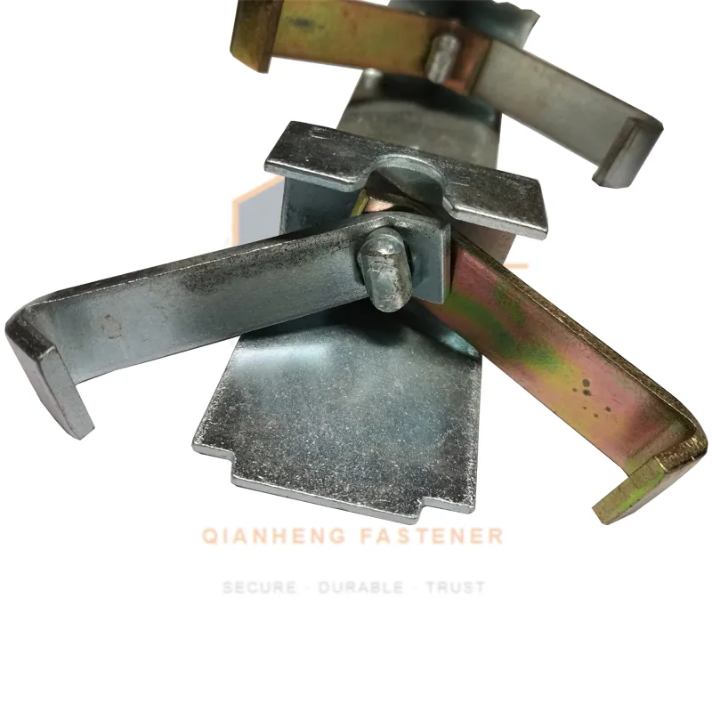
An H20 beam gives you almost nothing to grip. It is two timber flanges with a web between them, and the only reachable surface is the outside face and edge of an 80 mm flange that is already doing structural work. Everything the claw does follows from that constraint.
| Feature | What it does | What goes wrong if it is wrong |
|---|---|---|
| Hook throat | Sets which flange thickness and condition it will close on | Too tight and it will not seat on swollen or painted timber; too loose and it rocks under vibration |
| Tooth profile | Bites the flange face so the claw cannot slide along the beam | Rounded teeth slip; teeth that are too aggressive chew the flange and shorten beam life |
| Spring / preload | Keeps the hook closed before the wedge is driven | Weak spring and the claw falls off during handling, before anyone notices |
| Wedge | Converts the hook into a rigid clamp and takes up tolerance | Lost wedges are the single most common reason a claw goes unused on site |
| Body / tail | Ties the claw to the panel edge or the waling | Wrong tail and the claw cannot reach the waling it was bought for |
Two practical notes. Timber moves: an H20 flange that has sat in the rain is not the same dimension as one that has dried in a yard for a week, and site-painted or repaired beams vary more again. A throat dimension that only fits a new, dry beam will be a problem by the third cycle. And because the flange is the soft element, a tooth that is sharper than it needs to be does not make the joint stronger — it makes the beam weaker, and beams cost far more than claws.
3. What "stamped" actually means
Suppliers describe these parts as stamped, pressed or formed, and the words get used loosely. Here is the process that produces a claw, and why each step matters to the part you receive.
- Blanking. The flat outline is cut from steel strip or plate. Blanking leaves a characteristic edge: a smooth sheared band, then a fracture band, then a burr. This is where a claw's service life is largely decided, because a crack that starts at a blanked edge will run.
- Piercing. Holes for the wedge, the pivot and any fixing to the panel are punched. Punch-to-die clearance controls burr height; a burr on a wedge hole is what makes a wedge hang up and then get hammered.
- Forming. The hook is bent to shape in one or more hits. The bend radius relative to the material thickness is the parameter that matters: too tight and the outer fibre is strained past what the steel will take, too generous and the part loses stiffness and the throat opens.
- Coining the teeth. The tooth profile is impressed under high local pressure rather than cut. This is deliberate: coining work-hardens the tooth face, and a work-hardened tooth wears far longer than a soft one.
- Trimming and deburring. Edge cleanup. Cheap parts skip this step, and the burr is what cuts gloves and snags on beam flanges.
- Surface treatment. Zinc plating, or painting, or a mechanical finish. On a formwork site the coating is fighting constant wet alkaline exposure, so coating choice is a maintenance decision more than a cosmetic one.
Why stamping wins here, and where it does not
Stamping is not the cheap option that happens to work. For this part it is the correct one:
- Consistency. A progressive die produces the same geometry on part ten thousand as on part ten. When hundreds of claws per panel have to fit the same flange, consistency is worth more than strength.
- Grain flow. Forming follows the grain of the rolled steel around the bend instead of cutting across it, as machining would.
- Ductility in service. A stamped claw deforms before it breaks. A crew sees a bent claw and retires it. That visible warning is a safety feature.
- Weight and cycle time. Thin wall, low mass, fast to handle with one hand.
Where stamping is not the answer: the hook of a heavy H20 beam clamp that takes waler loads is a different job, and there a cast ductile iron hook is the better call. That is the logic behind the clamp we build with ductile iron hooks and a stamped body — cast where you need rigid, wear-resistant geometry, stamped where you need ductile, light and repeatable.
Die wear: the failure source nobody asks about
Every stamped part carries the health of the die it came off. As a die wears, the sheared edge quality falls, the burr grows, and the bend radius effectively tightens because material is not flowing the way it did when the die was new. The parts still look right. They simply crack earlier, at the bend, in the third or fourth cycle rather than the thirtieth.
This is the one question worth asking a stamping supplier: how often are the dies re-cut, and what is the inspection interval? A supplier who re-cuts on a fixed schedule and inspects edge quality per batch produces a different part from one who runs the die until it breaks. The parts look identical in a photo and behave differently on a wall.
4. Material notes
Our claws are stamped from Q235, a general structural carbon steel that is the right choice for a formed part of this size: it forms cleanly, welds if the design needs it, and is available in consistent mill supply. Where a buyer has a reason to go further, the options look like this:
| Material | When it is worth it | Trade-off |
|---|---|---|
| Q235 | Default for formed claws; adequate strength, excellent formability | Lowest cost, standard supply |
| Q355 (higher yield) | Where the design is driven by stiffness or a thinner section is wanted | Slightly tighter forming window, higher material cost |
| Alloy / spring steel for the spring element | Where the preload element is a separate part cycling constantly | Needed only if the spring is separate and heavily cycled |
| Cast ductile iron (e.g. QT450-10) | Hooks that take waler-level loads and must hold geometry | Heavier, rigid, can crack under impact; not a claw default |
Coating is the other half of the material decision. Zinc plating gives sacrificial protection against wet alkaline exposure and survives the abrasion of handling better than paint. Paint is cheaper and easier to touch up but wears off at the contact faces first, which is exactly where corrosion starts. Whichever you choose, the storage practice on site matters more than the coating: assemblies stored under cover and dried between pours outlast assemblies left standing in water regardless of finish.
5. How claws actually fail
We have yet to see a claw fail because it was not strong enough. The failures that put a claw in the scrap bin are these.
- Edge cracking at the bend. Starts as a hairline on the outer fibre of the hook bend and grows with each vibration cycle. Root cause is usually a worn die or too tight a bend radius, not overload. Visible if you look.
- Rounded teeth. The bite is gone, the claw slides along the flange under vibration, and the beam drifts. Occurs sooner on claws that have been hammered open rather than released by the wedge.
- Lost or loose wedge. The most common cause of a claw simply not being used. Wedges are small, they fall out of assemblies during stripping, and nobody orders spares.
- Crushed or chewed flange. The claw is fine; the beam is not. Over-driven hooks and over-aggressive teeth destroy the flange, and an H20 beam costs several hundred times what a claw costs.
- Corrosion and concrete buildup. Buildup on the throat changes the effective geometry so the claw no longer seats, and crews then force it — which bends the hook.
- Impact damage. Claws dropped from height onto a hard surface, or struck by a panel edge, get bent hooks. Bent means retired, not straightened: straightening cold-works the bend a second time.
Pre-use check, ten seconds
- Look at the bend radius — any crack line, retire it.
- Look at the teeth — rounded or flattened, retire it.
- Check the wedge is present and moves freely through the hole.
- Check the throat closes on the beam without forcing.
- Check the spring still holds the hook closed before the wedge goes in.
That is the whole maintenance programme, and it is worth more than any upgrade to the part itself.
6. What a claw actually costs you
The purchase price is not the cost. The cost is price divided by the number of pours the claw delivers before it is retired, plus the labour of crews fighting a part that does not seat.
| Scenario | Unit price | Cycles delivered | Cost per pour | Hidden cost |
|---|---|---|---|---|
| Cheap claw, dies not maintained | Low | Few | Can be the highest of the three | Crews forcing parts, panels delayed, beams damaged |
| Good stamped claw, maintained dies | Moderate | Several dozen | Lowest in practice | Almost none |
| Over-specified cast claw | High | Long | Middle | Heavier to handle, slower cycling, harder on flanges |
The middle row is where the value is, and it is not the row that wins a price-only tender. Which is the reason to write a specification.
7. Specification clauses you can send to suppliers
Paste this into a request for quotation. It turns "send me your claw" into something you can actually compare.
- Material and mill certificate. Body stamped from Q235 or equivalent; mill certificate with heat number available per batch.
- Plate thickness and tolerance. Stated nominal thickness with a tolerance; parts outside tolerance are rejectable.
- Bend radius. Supplier states bend radius relative to plate thickness, and confirms it is held across the batch.
- Edge condition. Blanked and pierced edges deburred; no burr that will snag or cut; edge crack inspection per batch, with a stated inspection method and sample rate.
- Tooth condition. Coined or otherwise hardened tooth face; no cracked or folded teeth.
- Die maintenance. Supplier states the re-grind interval for the tooling and the batch inspection interval.
- Coating. Zinc plating or stated alternative, with coating thickness or weight stated.
- Fit check. Sample parts must seat on a nominal 80 mm H20 flange in both dry and wet-swollen condition without forcing, and release without hammering.
- Cycle expectation. Supplier states the cycle count the part is specified for and the retirement criterion.
- Traceability and packing. Batch-marked, packed to a stated count, wedge and body packed together so wedges are not lost in transit.
- Spares. Wedges and springs available separately at a stated price.
Any supplier who can answer eleven clauses in writing is a different supplier from one who can only quote a price.
8. Related parts and further reading
The claw is one joint in a system, and it is worth knowing what the neighbouring joints are doing:
- H20 timber beam clamp — the heavy-duty partner, with ductile iron hooks for the waler connection: /products/h20-wooden-beam-clamp
- Timber beam claw connectors — the product page for the parts discussed here: /products/wooden-beam-claw
- Stamped claw buying guide — the shorter procurement version, focused on what to check before ordering: /blog/timber-beam-claw-connector-guide
- Cast iron or pressed steel for H20 clamps — how the material split works at the next joint up: /blog/h20-beam-clamp-cast-iron-vs-pressed
What we do differently
We stamp claws on maintained tooling and we say so, because die maintenance is the variable that decides whether a claw survives thirty cycles or three. We hold 300 tonnes of stock across the fastener range, run threading, pressing and finishing in house on a 5,000 m² site, and ship stock sizes within 3 days and made-to-drawing sizes in 7–15 days under ISO 9001, ISO 14001 and ISO 45001. Minimum order quantity is 500 pieces, and we pack wedges and bodies together because we have watched too many wedges disappear in transit.
If you are specifying this part for a fleet rather than a single pour, send us the eleven clauses above and we will answer them in writing.
Full specifications and contact details: qianhengform.com