
Basement and Below-Grade Walls: Water-Stop Tie Rod Selection and Detailing
At a glance: a below-grade structural wall develops a leakage path at the tie-rod through-point whenever the continuous steel element embedded in the concrete provides a capillary migration route for moisture. A water-stop tie rod transmits the tensile load and simultaneously interrupts that migration path at the identical location, while the five-section configuration permits the lost-end sections to be recovered and re-used after the pour cycle. Dimension the rod to the hydrostatic pressure acting at the retained depth rather than to customary practice — see OSHA's concrete construction eTool for the hazard background of working with fluid concrete under pressure, and the EU construction-products framework for the conformity context that surrounds below-grade specification.
Basements, pump rooms, pools and retaining walls all share one recurrent failure mode: water locates the tie-rod through-point and migrates through it. This guidance examines how a water-stop tie rod suppresses that migration path, why the five-section configuration is preferred for component recovery, how the rod is dimensioned against hydrostatic pressure at depth, and how spacing is detailed so the completed structure remains dry in service.
Water-stop tie rod is a tie that transmits the load across the wall and interrupts the through-path of moisture at the identical location, utilising a moulded PVC or rubber element positioned on the core. Recovery refers to the proportion of the assembly that can be re-used on the following cycle instead of being sectioned and abandoned. Hydrostatic pressure means the pressure exerted by a fluid at equilibrium due to the force of gravity, calculated as the density of the fluid multiplied by the height of the retained liquid. Safety factor is the ratio between the rated load and the load the part will actually carry; divide the rated yield by 2 to 3 before comparing with the calculated load per tie.
1. Why below-grade walls leak at the tie.
A standard tie rod secures the two form faces together, yet it simultaneously establishes a continuous steel channel traversing the wall. After the form is struck the projecting ends are sectioned flush, and that cut steel can subsequently act as a capillary conduit for moisture once the concrete has cured and undergone shrinkage. Within a basement the wet side is permanent, so the through-point is precisely where infiltration originates.
Water-stop tie rod is a tie that transmits the load across the wall and interrupts the through-path of moisture at the identical location, utilising a moulded PVC or rubber element positioned on the core. The wall remains dry after the form is struck because the steel route no longer extends continuously from the wet face to the dry face.
2. How the water-stop tie blocks the path.
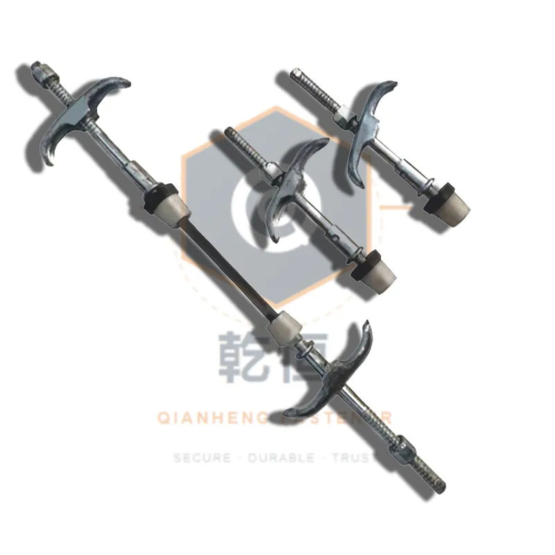
The sealing element on the core constitutes the barrier. It resides within the wall thickness and severs the continuous steel route, so that even after the ends are sectioned no straight capillary channel remains connecting the wet side to the dry side.
| Feature | Standard tie | Water-stop tie |
|---|---|---|
| Load path | Steel through the wall | Steel through the wall |
| Water path | Continuous after cutting | Broken by the stop |
| After strike | Ends cut, path remains | Path sealed at the stop |
| Best use | Above-grade, dry walls | Basements, pools, retaining walls |
Our three-part water-stop tie rod page shows the component layout, and the cast-iron water-stop nut we produce in ductile iron QT450 is rated to a documented breaking load with the tensile test result supplied. The measured breaking load is verified to NIST's material measurement discipline, the same calibration basis used across our range, and our verification methodology applies batch tensile testing to every finished part before dispatch.
3. Five-section vs one-piece: recovery matters.
The five-section configuration comprises a central water-stop core plus two threaded end sections. After the concrete hardens, the outer ends are unscrewed and recovered for the subsequent pour; the short central core remains embedded and is then capped or sealed.
Recovery is the proportion of the assembly that can be re-used on the following cycle instead of being sectioned and abandoned. A one-piece water-stop tie is cut and left in situ, so none of the rod is recovered. The five-section configuration recovers the two threaded ends, which is why it is normally the lower total-cost option across a repeat basement programme.
4. Sizing to hydrostatic pressure at depth.
Hydrostatic pressure constitutes the conservative ceiling for below-grade work. Normal reinforced concrete weighs approximately 24 kN/m3 (see Engineering Toolbox concrete properties), so the pressure at the base equals density multiplied by retained height. A 3 m wall yields about 72 kPa; a 4 m wall yields about 96 kPa; a 5 m wall about 120 kPa.
Safety factor is the ratio between the rated load and the load the part will actually carry; divide the rated yield by 2 to 3 before comparing with the calculated load per tie. Our own datasheets indicate a D15 system near 150 kN yield and a D20 near 230 kN, so at 4 m a D20 is normally the safer selection.
| Retained height | Base pressure | Load at 1.0 x 1.0 m | D15 working (SF 2) | D20 working (SF 2) |
|---|---|---|---|---|
| 3 m | 72 kPa | 72 kN | 75 kN | 115 kN |
| 4 m | 96 kPa | 96 kN | 75 kN | 115 kN |
| 5 m | 120 kPa | 120 kN | 75 kN | 115 kN |
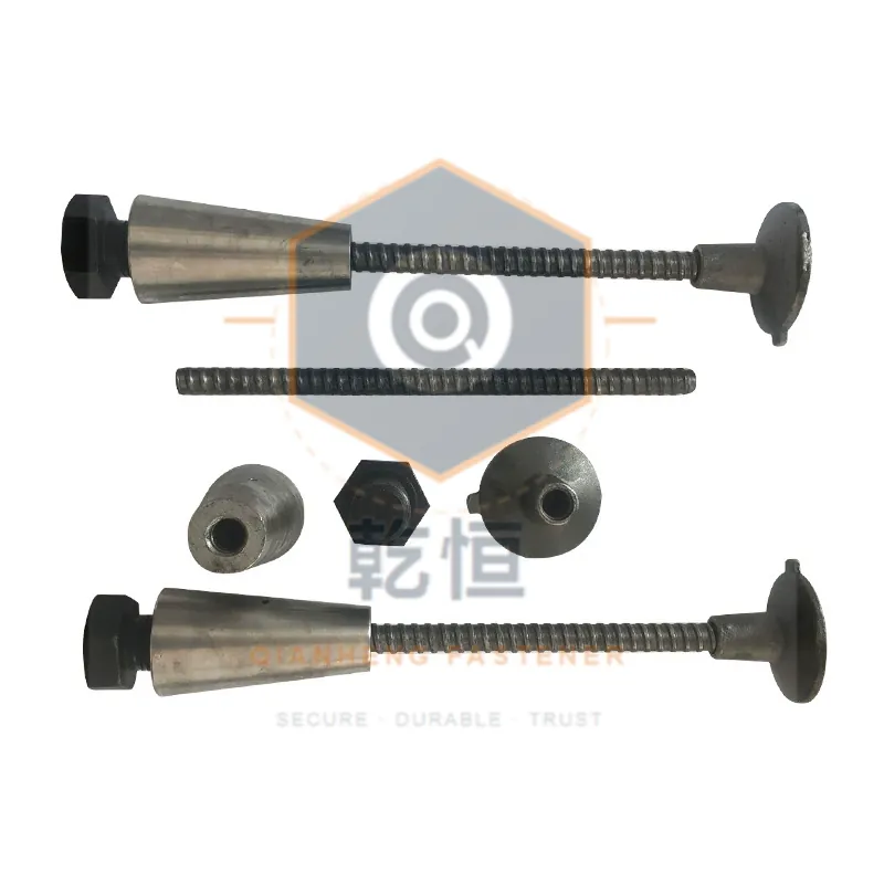
Worked example: a 4 m basement subjected to 96 kPa, with a grid of 1.0 x 1.0 m, yields 96 kN per tie. The D15 working load at a safety factor of 2 is approximately 75 kN, which falls below the imposed duty, so the D20 at approximately 115 kN constitutes the correct selection. The square base plate and the climbing cone assembly must subsequently be verified on the identical basis.
Standard basis: EN 13670
5. Detailing: where and how often.
Position a water-stop tie at every through-point of a below-grade wall, because no element on a basement face remains exempt from moisture exposure. Spacing adheres to the identical pressure-grid arithmetic applied to any wall, with the grid tightening progressively as the retained height increases.
- Basements and pump rooms: water-stop tie at every point, D20 above about 3 m retained height.
- Pools and water tanks: water-stop tie throughout, with the stop rated for continuous immersion service.
- Retaining walls: water-stop tie on the retained (earth) side; the drained side may utilise a standard tie.
- Recovery programme: specify the five-section configuration so the threaded ends return for the next pour.
The ACI 347 formwork practice adopts the same hydrostatic starting point before applying temperature and pour-rate reductions, so the grid derived from the table above is the conservative ceiling from which to detail.
Standard basis: ACI 347 formwork practice
6. Procurement practice.
State the four real inputs in the RFQ: retained height, pour rate, concrete temperature, and intended tie spacing. For below-grade work also state that every through-point requires a water-stop tie and whether the five-section recovery configuration is specified.
We hold approximately 300 t of fasteners in stock and dispatch stock items within 3 days; custom diameters, lengths and coatings run 7 to 15 days. Every finished part is tensile-tested against its specification and the result travels with the batch. Trade terms are EXW, FOB, CIF or DDP depending on who controls the freight, and export packing utilises VCI paper and strapped crates to prevent transit corrosion. Each specification is reviewed by our quality engineer before release.
For a below-grade programme, agreeing the water-stop specification and the recovery configuration with our engineering team before the first pour avoids the infiltration that becomes visible only after the form is struck.
FAQ.
What is the difference between a water-stop tie rod and a standard tie rod?
A standard tie rod carries the load but leaves a continuous steel path through the wall; once the form is struck and the ends are cut, that path can become a capillary route for water. A water-stop tie rod carries the load and also blocks the through-path at the same point with a moulded PVC or rubber stop, so the wall stays dry after the form is struck.
Why choose the five-section type over a one-piece water-stop tie?
The five-section type lets the two outer 'lost ends' be removed after the concrete hardens, leaving a short central core that is capped or sealed. That recovers the threaded ends for reuse on the next pour and leaves a smaller, easier-to-seal remain in the wall, whereas a one-piece tie is cut off and abandoned in place.
How do I size the rod for a 4 m basement wall?
Use hydrostatic pressure as the ceiling: about 24 kN/m3 times the retained height, so 4 m gives roughly 96 kPa at the base. Pick the rod and spacing so the allowable working load, the rated yield divided by the safety factor of 2 to 3, exceeds the load per tie from that pressure and grid. At 4 m a D20 is normally the safer choice over a D15.
---
About the author — Qianheng's formwork engineering team designs and tensile-tests tie-rod systems for contractors across the EAEU, the Middle East and Southeast Asia. *Reviewed by our quality engineer before release.*
About us: This article covers water-stop tie rod selection and detailing for basements and below-grade walls, checked against our engineering standards. We hold 300 t of fasteners in stock and dispatch within 3 days. Our contact page provides direct access to our engineering team, and the about page documents our company's capabilities and history. This article was reviewed by the Qianheng Formwork Engineering team.