
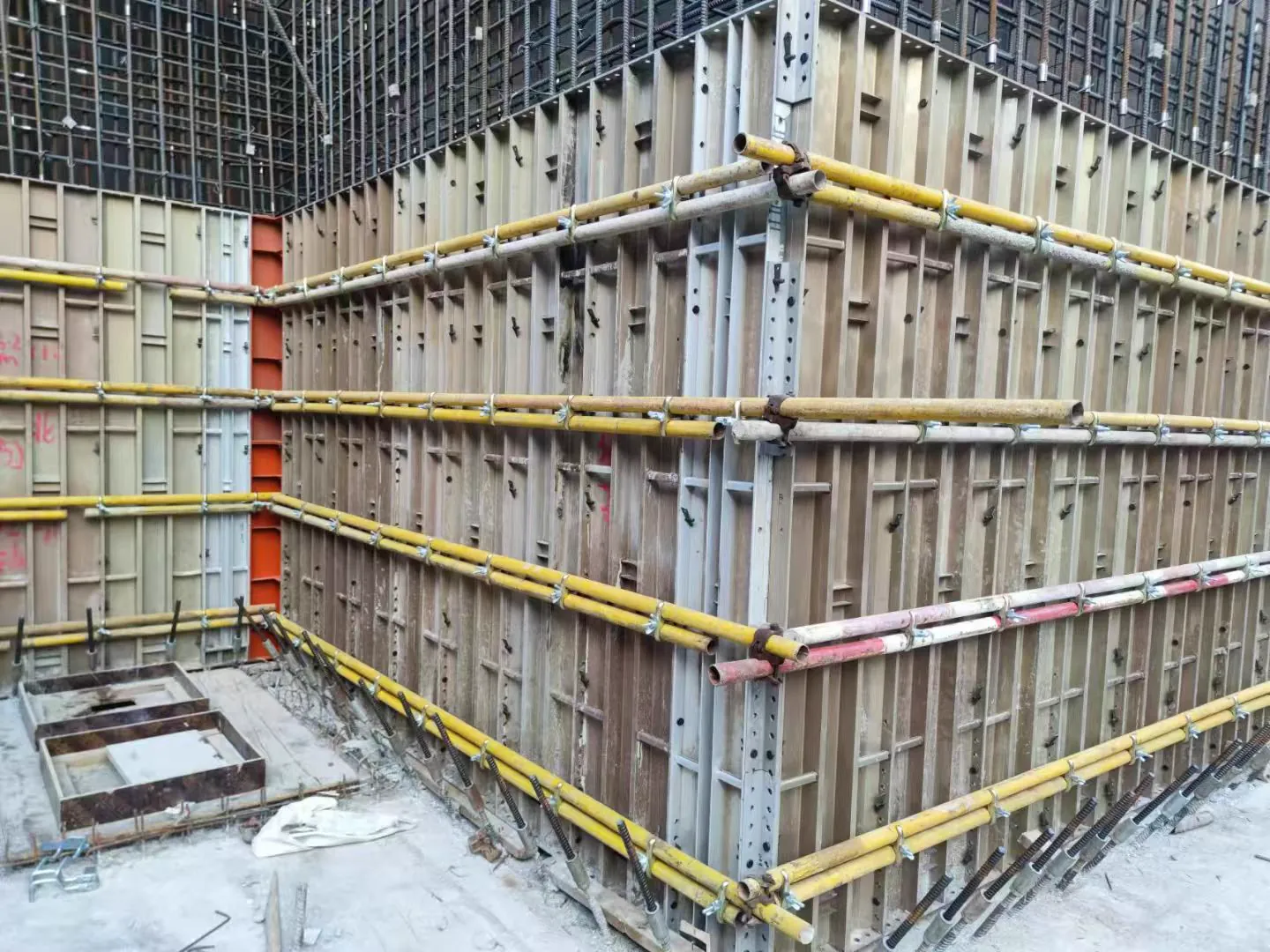
Most reported "fastener failures" are not material failures. They are a load path misjudged or an assembly detail skipped. Knowing the mode tells you which control would have prevented it.
1. Tie rod rupture at the first engaged thread
CAUSE: overload, usually from underestimated lateral pressure on a fast pour or cold concrete, combined with a reduced section at the thread root. Fatigue from reuse can start a crack at the same location.
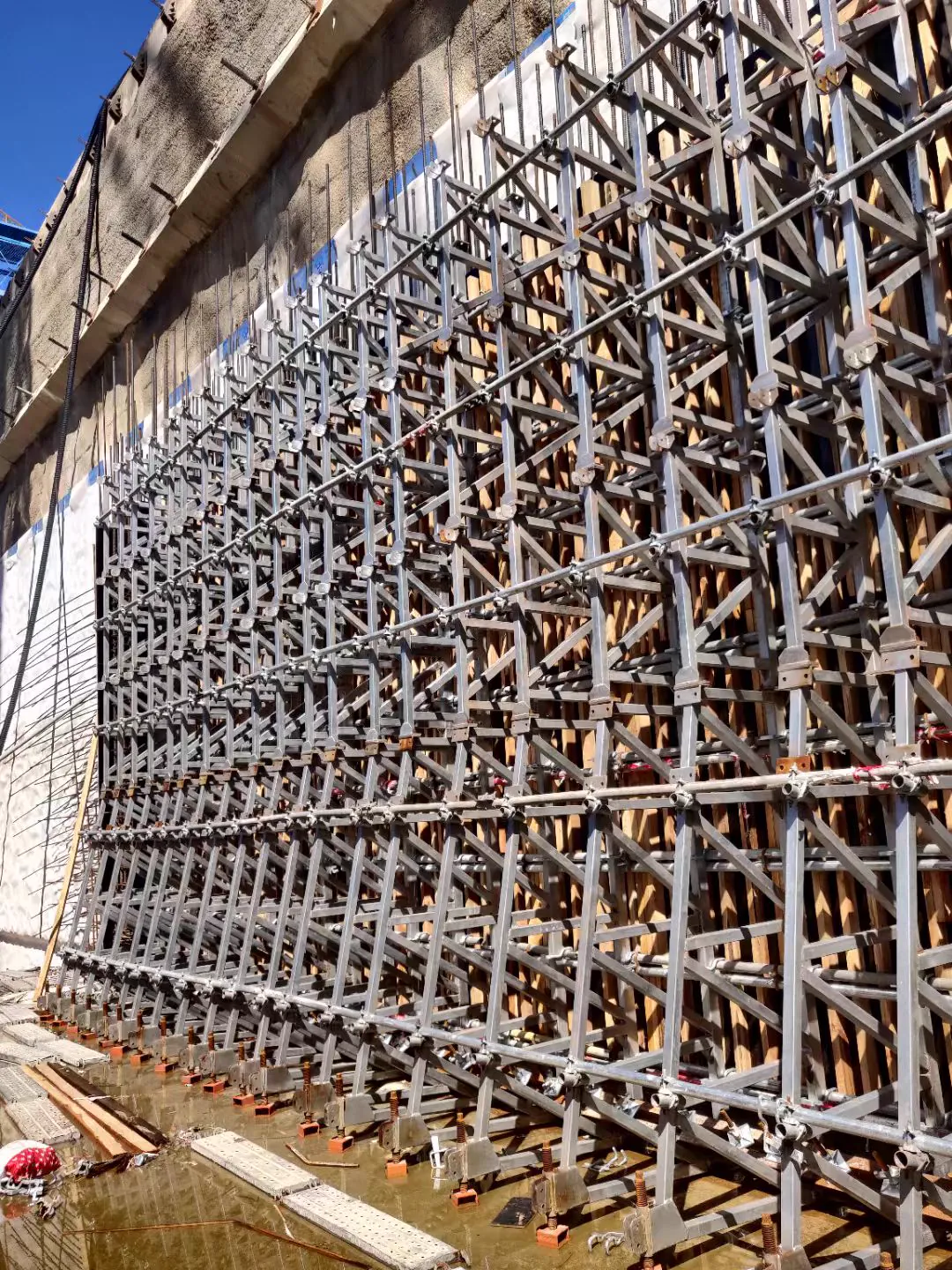
CONTROL: correct pressure calculation, tighter spacing in the lower zone, rated capacity certificate, and inspection of the first three threads before each reuse.
2. Nut back-off under vibration
CAUSE: internal vibration transmitted through the formwork, insufficient thread engagement, or a nut reused until the fit is loose enough to walk.
CONTROL: specify minimum engagement — commonly one diameter or the nut height, whichever is greater — use disc or wing nuts designed to grip the face, and check fit by hand on a sample before each reuse.
3. Cone pull-out
CAUSE: cone seated proud of the concrete face so only a thin shell resists the load, or an anchor set too shallow.
CONTROL: anchor depth gauge or setting tool, alignment tolerance, and a first-lift check on the actual wall before production pours.
4. Thread stripping
CAUSE: pitch mismatch between rod and nut, cross-threading during assembly, coating build-up on threads, or a nut of lower class than the rod.
CONTROL: gauge check at goods-in, matched class for rod and nut, tapped-oversize nuts for hot-dip galvanized assemblies, and a hand-thread test before each reuse.
5. Waler or panel failure masking a sound tie
CAUSE: the tie was correctly rated but the waler bent, the panel skin deflected, or the tie hole elongated. The tie then pulls through a failed supporting element.
CONTROL: verify the whole load path — panel, waler, tie and anchor. Check waler splices and the bearing of waler against panel.
6. Corrosion-driven rupture
CAUSE: for permanently embedded elements, insufficient coating thickness, coating damage during handling, or a galvanic couple with bare steel in the same assembly.
CONTROL: specify HDG 45-85 µm for embedment, protect coating at handling points, avoid mixing coated and bare parts in one joint, and inspect before the pour since embedment is irreversible.
The pattern behind all six
Every mode has a cheap inspection that catches it before the pour and an expensive consequence after. The practical controls are the calculation, the goods-in gauge check, the hand assembly check and the photograph before loading. None requires special equipment; all require someone assigned the task by name.