
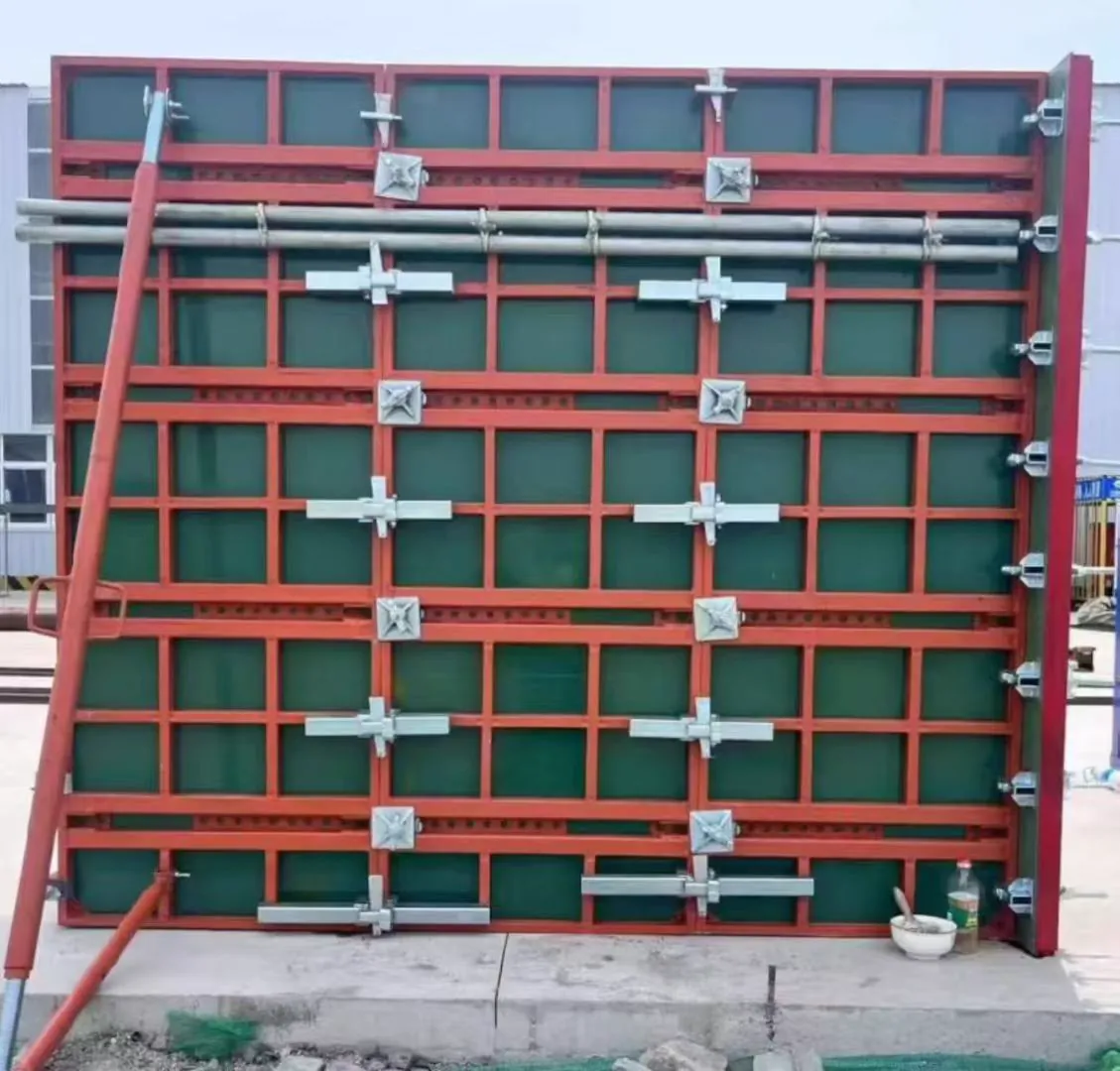
Pin and Wedge Joints: What Holds a Steel Panel Square
> In brief > - The pin resists shear; the wedge only stops the pin walking out. > - Capacity is set by the hole, not by the pin's material grade. > - Hole ovality shows up as steps in the finished face. > - A missing pin cannot be substituted with rebar.
Modular steel formwork is sold on its panel, and it fails at its joints. The panel is a stiff plate with a known bending capacity; the joint between two panels is a set of pins in clearance holes, and everything about the finished wall's straightness and the joint's capacity comes from how well those holes line up and how well they are maintained.
Our own production and test data are available on request — see how our factory works and contact the engineering team for the documents behind any figure quoted here.
Pin and wedge is the standard joint for modular steel panels: a steel pin through aligned holes in the flanges of two adjacent panels, retained by a tapered wedge. Shear plane is the interface where the two panels would slide past each other. Hole clearance is the difference between pin diameter and hole diameter, and it is the single largest influence on joint stiffness. Ovality is the elongation of a hole after repeated impact driving, measured as the difference between its longest and shortest internal dimensions.
The load path, stated plainly
Concrete pushes the panel outward. At a vertical joint between two panels, the two panels want to move by different amounts, and the joint has to resist that difference. That resistance is shear across the pin, on two planes — one either side of the interface — so a single pin in a through-joint works in double shear.
| Pin | Typical material | Shear area, double | Indicative shear capacity | Joint it suits |
|---|---|---|---|---|
| 12 mm | Q235 / 4.8 | 226 mm2 | ~30–40 kN | Standard wall panels, 1.2 m wide |
| 16 mm | Q235 / 4.8 | 402 mm2 | ~55–70 kN | Heavy panels, tall single lifts |
| 20 mm | 45# / 8.8 | 628 mm2 | ~110–140 kN | Column and bridge panels |
Treat those figures as order of magnitude for planning a joint layout, not as a certificate. The real capacity of the joint is usually decided by the hole and the flange, not the pin: a 16 mm pin in a hole that has been driven oval to 18 mm bears on a line rather than a cylinder, and the flange around the hole starts to yield before the pin shears.
Why the wedge is not a fastener
A wedge does one job: it stops the pin sliding out under vibration. It is tapered so that it locks against the pin by friction, and the taper angle is smaller than the friction angle of steel on steel, which is what makes it self-holding.
That has two practical consequences, and both are routinely ignored.
A tight wedge is not a tight joint. Site habit is to assess a joint by hitting the wedge. A joint with a fully driven wedge and a pin sitting in an oval hole feels solid and is slack. The check has to be on the pin and the hole, not on the wedge.
A wedge that needs a hammer to remove is over-driven. Wedges driven past their seat deform the pin, deform the hole, and are then removed with a crowbar that does the rest of the damage. The correct seat is firm contact, not maximum depth.
Hole condition is the real specification
Every panel in service has holes that started round and became something else. The tolerance that matters is not in the catalogue, it is the number a buyer never asks for.
| Hole state | Effect on joint | What to do |
|---|---|---|
| Round, clearance 0.5–1.0 mm | Pin bears evenly, faces stay flush | Normal service |
| Round, clearance 2 mm or more | Faces step under load; pin rattles | Replace with an oversize pin, or bush the hole |
| Oval, long axis less than 1.5 x pin | Step becomes visible in the face | Sort these panels to internal joints, not exposed faces |
| Oval, long axis over 1.5 x pin | Capacity unpredictable, step obvious | Withdraw the panel from structural use |
| Torn or cracked through the flange | No reliable capacity | Scrap |
The sorting rule is the one worth remembering. A worn panel is not necessarily scrap — it is a panel that should not be on a fair-faced or single-sided face, where a 2 mm step is a defect the client will reject. Put it in a position where the step is hidden or where the joint is not the governing element. That is the same logic as managing hardware inventory and recovery, applied to panels rather than to rods.
Pin and wedge versus bolt clamp
Two ways to make the same joint, and they are not alternatives at the same price point.
| Criterion | Pin and wedge | Bolt clamp |
|---|---|---|
| Assembly speed | Fast, one hand, no tools | Slower, needs a spanner or impact driver |
| Clamping force across the joint | None — the joint closes by pin fit only | Positive, set by torque |
| Tolerance to hole wear | Poor, clearance turns into a step | Better, clamp pulls the flanges together |
| Loss rate on site | High — wedges are small and drop | Lower, the clamp stays on the panel |
| Best use | Regular modular wall, high panel count | Corners, transitions, single-sided faces |
The practical conclusion most of our customers reach is to use pins and wedges on the run and keep clamps for the corners and the first panel of a lift, where the geometry is set. A run of panels all pinned is fast and straight if the holes are good; a corner made of pins alone has nothing to pull the two faces into alignment, and that is where the clamp earns its place. The same reasoning drives the steel waler splice and connection detail, where alignment rather than shear is the governing requirement.
What to write in a purchase specification
Four lines cover the part, and one of them is the one buyers forget.
- Pin diameter and material, matched to the panel hole — 12, 16 or 20 mm, with the grade stated.
- Pin length so the wedge seat falls outside the flange, not inside the hole.
- Wedge taper and material, and whether the wedge is captive or loose. Captive wedges cost more and lose far less.
- Hole tolerance on the panel, stated as a maximum clearance and a maximum ovality — this is the line that is normally absent, and it is the one that decides whether the joint performs in year three.
Our steel frame system components are supplied with pins and wedges matched to the panel hole, and the quick clamp and heavy duty clamp cover the corner and transition positions where a pin joint alone will not hold alignment. The frame connector covers the T and cross junctions that a straight pin joint cannot make.
If you are specifying a modular system from scratch, the joint is worth more attention than the panel gauge. Panels are delivered to a drawing; joints are assembled on site by whoever is available. The complete guide to formwork fasteners puts the joint hardware in the context of the whole assembly, and thread damage repair limits covers the same question — when a worn part can be recovered and when it has to be replaced — for the threaded side of the system.